final-project-dream-team
final-project-skeleton
* Team Name: Dream Team
* Team Members: Abhik Kumar, Shreyaans Singh, Stanley
* Github Repository URL: https://github.com/upenn-embedded/final-project-dream-team
* Github Pages Website URL: https://upenn-embedded.github.io/final-project-dream-team/
* Description of hardware: Microcontroller:
        1. Atmega328PB Xplained Mini - 4
        2. Zigbee Xbee S2C - 2
        3. IMU - ADXL335 - 2
        4. Neopixel Ring - 3
        5. Bit addressable LED strip - 1
Final Project Report
1. Video
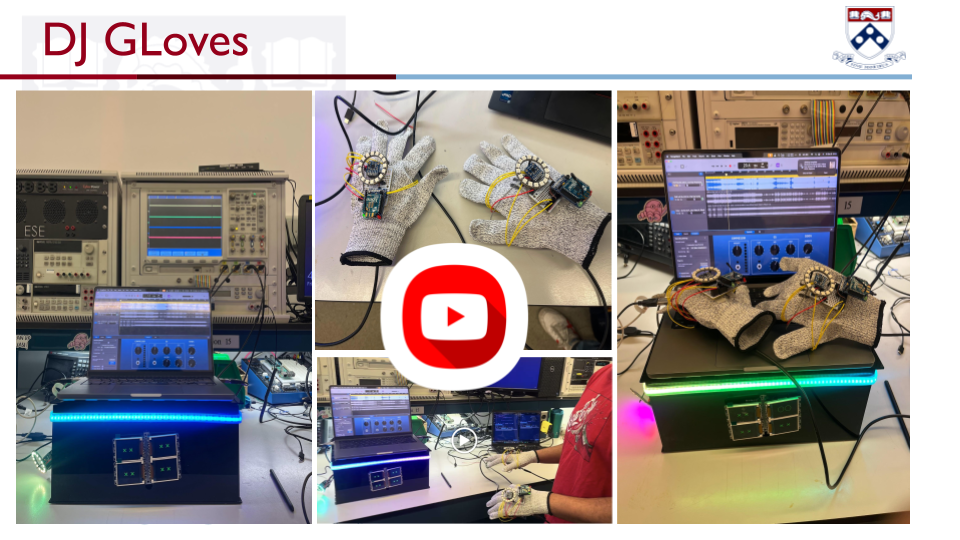
DJ GLove
Project Overview
The video demonstrates the full functionality of our project, showcasing the seamless integration of the sensor controller and its interaction with the system. Below are the key features and functionalities presented:
Key Features
- Wireless Data Transmission:
- Sensor data is acquired and transmitted wirelessly from the gloves to the receiver node located inside the prop stage.
- Interactive Hand Movements:
- The functionalities of the system are showcased by moving the hand and dynamically altering the modularity of the music being played.
- Real-time Processing:
- The project explains how sensor data is processed in real-time and converted into distinct states that control the musical output.
- Real-time Feedback:
- A real-time feedback system is implemented using the Neopixel ring on the gloves, where each state is mapped to a specific color.
- Additionally, the action of each state (e.g., volume up) is displayed on the LCD screens located on the stage.
Video Demonstration Highlights
- Sensor Integration:
- Illustrates the seamless connectivity between the gloves and the prop stage.
- Dynamic Modularity:
- Demonstrates how hand movements influence and modify the music in a dynamic and responsive manner.
- System Explanation:
- Provides an in-depth explanation of the technical implementation, including how:
- Sensor data is acquired and transmitted wirelessly.
- Data is processed and mapped into specific states to control the music.
- Provides an in-depth explanation of the technical implementation, including how:
Additional Notes
- The system showcases a creative and technical approach to integrating sensor technology with musical modularity.
- Future enhancements could involve extending compatibility with more music platforms or improving the sensitivity of state recognition for finer control.
2. Images
- Images of the Gloves:
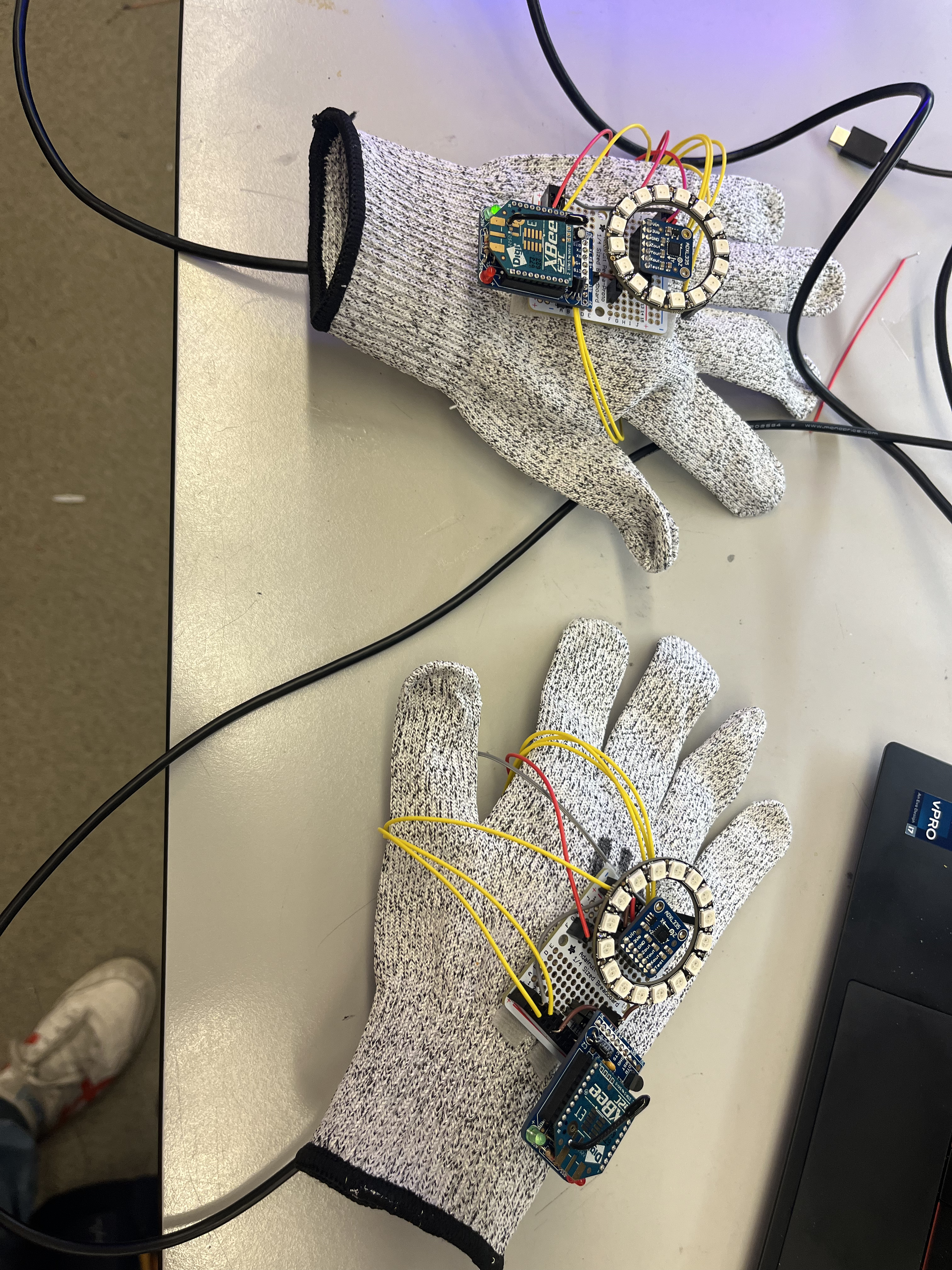
We can see both gloves, each equipped with an ATmega328PB microcontroller on the palm surface, along with a Zigbee X2C transceiver, a Neopixel ring, and an ADXL335 accelerometer on the knuckle side of the glove.
- Images of the Stage:
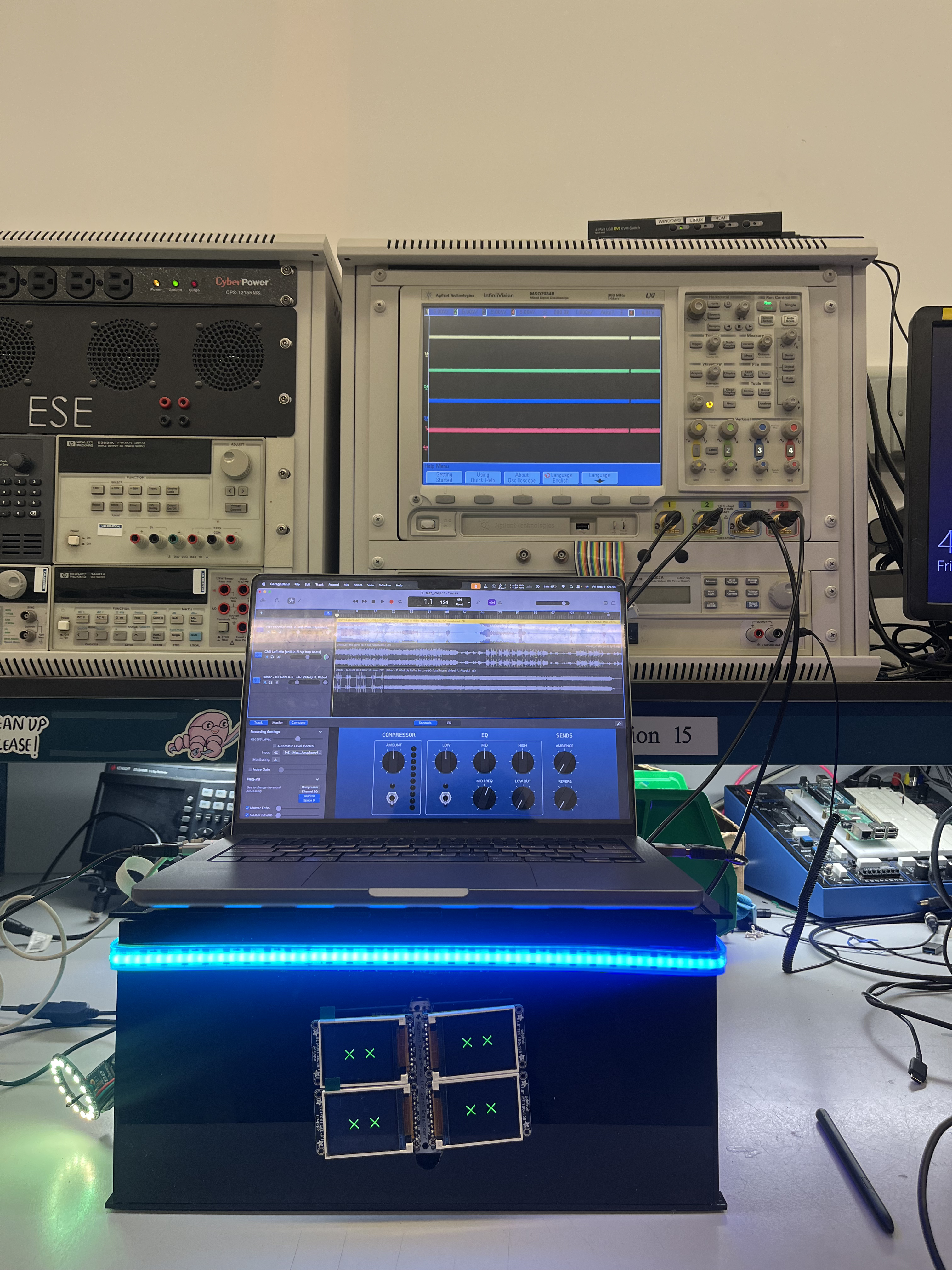
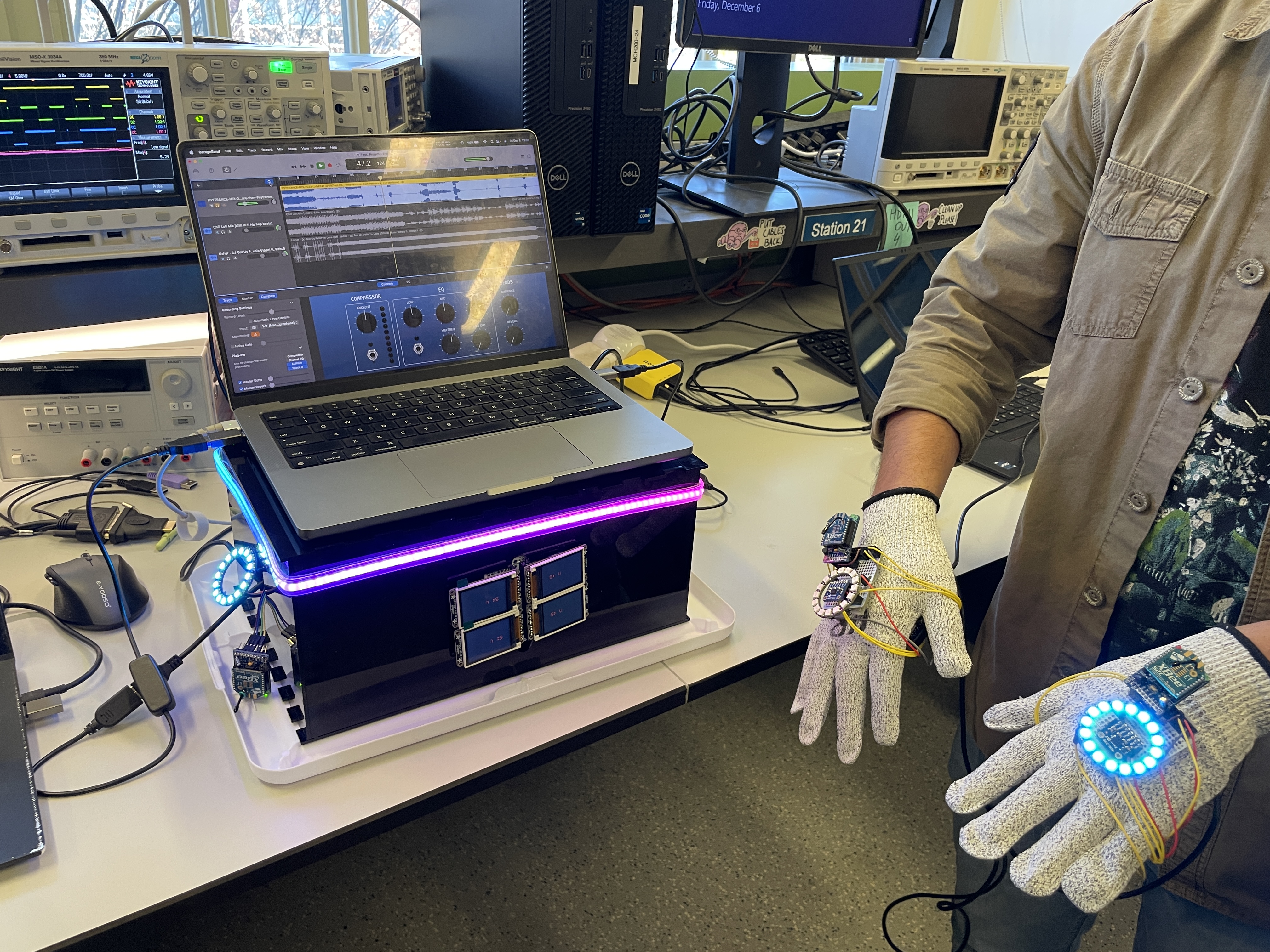
The stage is large enough to accommodate a MacBook Pro. Furthermore, the stage features an LED strip to make it more colorful and visually appealing. Inside the stage, we have two ATmega microcontroller: one acting as the receiver node and the other communicating with the receiver via GPIO pins to send MIDI signals to the laptop.
- Images of the full project working:

The full project being used:
The image above illustrates how the user interacts with the project, while the video demonstrates how the user can control the music through hand movements.
3. Results
Key Achievements
- Successfully interfaced a 3-axis IMU (ADXL335) to detect gestures and orientations using ADC and interrupts.
- Developed firmware supporting wireless communication via Zigbee X2C, enabling real-time transmission of states mapped to IMU data.
- Successfully translated the transmitted data into accurate midi commands
- Implemented a Python bridge to process MIDI control signals and integrated it with GarageBand for seamless music control.
- Designed and operated a circuit to run four LCD screens over a single SPI line, achieving a cohesive large-screen effect.
- Utilized Neopixel LED rings and LED strips for real-time visual feedback based on gestures and audio cues.
- Demonstrated dynamic modification of audio modalities, such as pitch and volume, using hand gestures.
3.1 Software Requirements Specification (SRS) Results
Revisiting SRS at the End of Our Project
-
SRS 01 – We successfully interfaced a 3-axis IMU that provides ADC data, and we sampled this data at 200ms intervals. We utilized ADC and interrupt to make the high sampling rate viable. Further, we used techniques such that we only registered a viable change in the IMU sensor data and only this data would be send wirelessly.
-
SRS 02 – We developed firmware to support wireless communication using the Zigbee X2C module, which operates on UART to transmit the states mapped to IMU data in real-time. We pivoted from using a Bluetooth sensor to a Zigbee module. We implemented queues, and state change functions so that only useful changes in states are relayed over wireless communication. Further, with the 3-axis nature of the ADXL 335 sensor, we had to implement queues so that we could administer all 3-axis changes if they have occurred and relay them one-by-one in order to keep the user-experience and functionality practical.
-
SRS 03 – The firmware we developed can send MIDI signals to any software compatible with MIDI protocol. Additionally, we implemented a Python bridge to accept MIDI control signals over UART from an ATmega microcontroller. In our final implementation, we used GarageBand instead of Mixxx DJ software. We were able to verify these states were being transmitted correctly over both Atmegas using logic analyzers, serial monitor and oscilloscopes
-
SRS 04 – We successfully deployed firmware capable of changing audio modalities in GarageBand based on hand orientation and gestures. We were able to confirm the changes were happening accordingly by using the garage bands GUI.
-
SRS 05 – We interfaced four LCD screens over SPI that displayed real-time changes in the audio modalities occurring in the music.
-
SRS 06 – Using our firmware, we successfully utilized the Neopixel LED ring on the glove to change colors according to the hand’s gestures and orientation.
We were not able to leverage SPI communication and interface a nrf24L01 sensor with the amtega328PB for our wireless communication.
Further, we did not utilize the IMU ADXL345 that uses I2C communication.
3.2 Hardware Requirements Specification (HRS) Results
Revisiting HRS at the End of Our Project
-
HRS 01 – We used four ATmega328PB microcontrollers in total: one on each glove and two inside the stage.
-
HRS 02 – We utilized an ADXL335 sensor to detect gesture and orientation changes, leveraging ADC and interrupts for accurate data acquisition.
-
HRS 03 – We successfully designed a circuit to run four LCD screens over a single SPI line and arranged them in an orientation to effectively create a large screen effect.
-
HRS 04 – We used the laptop’s speakers to play music and demonstrate the changes in audio modalities.
-
HRS 05 – We fully controlled the color sequencing, brightness, and intensity of the LED strip and the Neopixel rings by utilizing timers.
-
HRS 06 – We modified this hardware requirement by using an XBEE S2C (Zigbee) module to establish real-time wireless communication instead of the Bluetooth HC05 module.
The USB chip (ATMega32U4) on the XPLAINed board cannot be programmed and hence were not able to use our Atmega to direclty communicate with the garage band software and had to implement a python bridge. (Hard booting the firmware in the ATmega32U4 will remove the programming and debugging capabilities of the mEDBG. If the EEPROM is altered the mEDBG would not be recognized by compiling Studio anymore. Leaving the XPLAINed MINI board unusable.)
Further, we were unable to use USART1 via PB3 and PB4 pin on the Atmega328PB and hence we had to create a GPIO pin bridge to communicate between two atmega’s instead of using only 1 at the receiver node.
4. Conclusion
This project was an enriching experience that allowed us to blend embedded systems, wireless communication, and real-time control into a functional and creative system aka “DJ Gloves”. We are proud of successfully integrating multiple hardware components, such as the ADXL335 sensor, Neopixel LED rings, and LCD screens, to create an interactive platform that dynamically controlled music. The decision to pivot from Bluetooth to Zigbee for wireless communication significantly improved reliability, showcasing our adaptability in problem-solving.
One of our major accomplishments was designing a robust pipeline for transmitting real-time sensor data and mapping it to states that controlled audio modalities in GarageBand. However, challenges, such as the inability to program the USB chip on the XPLAINed board and limitations in utilizing USART1 on the ATmega328PB, required us to implement innovative workarounds, including a Python bridge.
This project reinforced the importance of planning for hardware constraints and adaptability. Future steps could involve enhancing modularity, supporting more music platforms, and optimizing sensor precision.
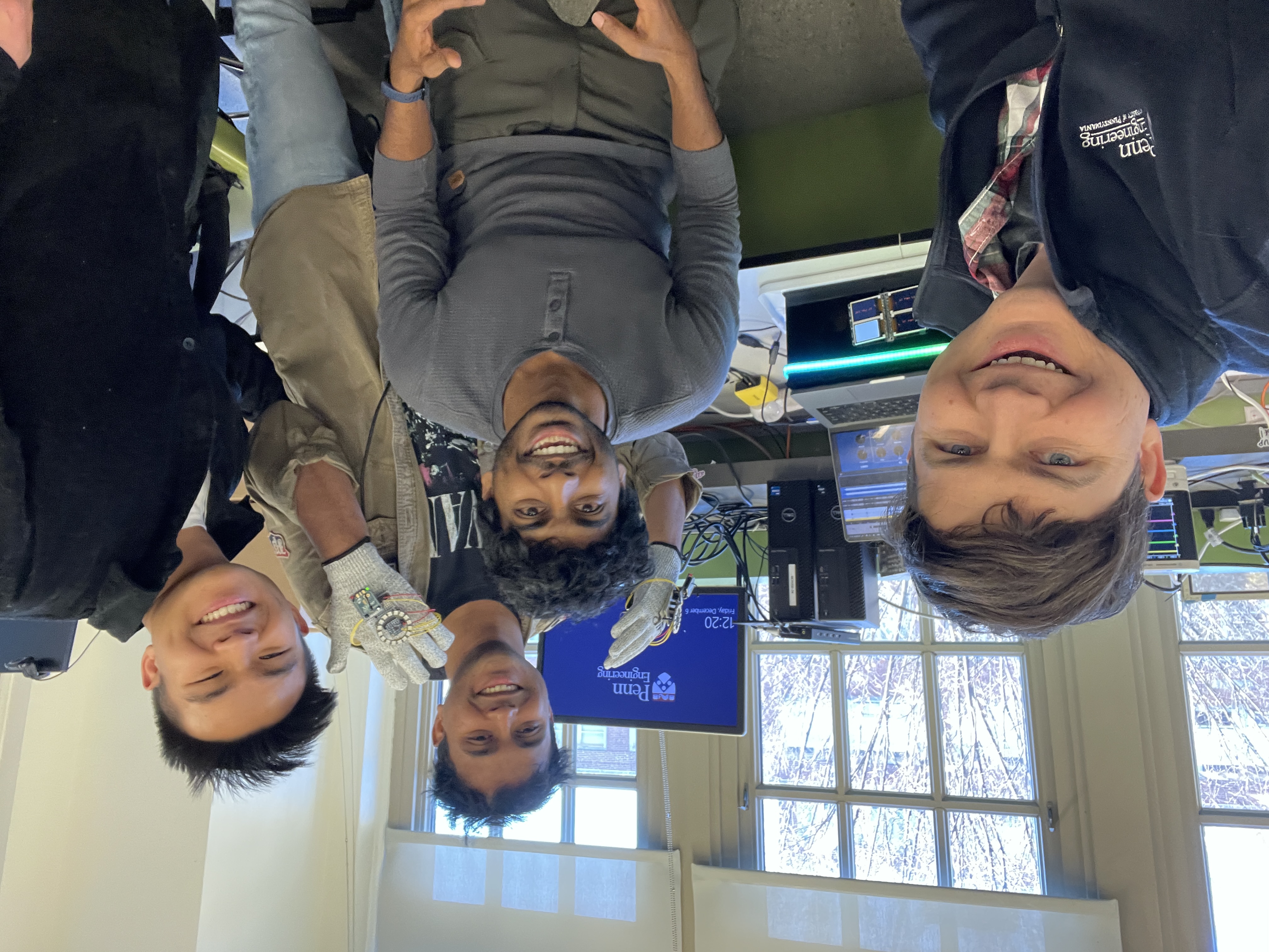
5. Team Photo
5. Codes
All the used codes are uploaded in the github and linked here:
MVP Demo Framework
1) Submit your GitHub URL: https://github.com/upenn-embedded/final-project-dream-team
2) Show a system block diagram & explain the hardware implementation:
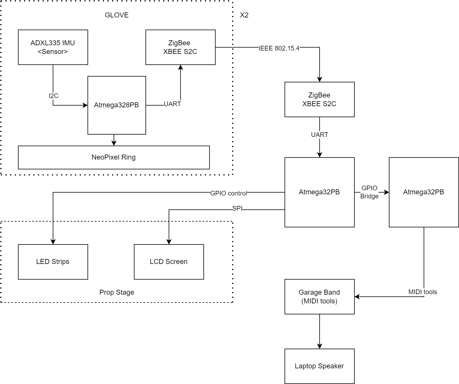
The above block diagram can be best explained in 4 stages of how the proposed embedded system works:
- The input stage (Gloves): a. The ADXL335 sensor (Inertial movement unit): capable of measuring 6 degrees of freedom. (Currently only utilizing 3 dof) b. Zigbee Module: Enables wireless transfer of IMU measurement (Converted to states) to the ATmega32PB (which has a Zigbee receiver node). c. NeoPixel Rings: Mapped to states and changing intensities and modalities of the sound.
All of these interfaced over the same Atmega328PB. ZigBee -UART–> Atmega328PB. IMU(ADXL345) -I2C–> Atmega328PB. NeoPixel -GPIO(PWM)–> Atmega328PB.
-
Microcontroller - Atmega328PB: a. Here the data sent via Zigbee (802.15.4) is mapped to finite states. This is done to de-couple or abstract the input from the output or the actuation. b. These mapped states are sent over to another Atmega328PB over a GPIO bridge. The second Atmega328PB maps these finite states to an LUT of MIDI control mnemonics that help us change the modalities of the music.
-
Laptop (Music Mixing and MIDI tools): a. A python MIDI bridge is implemented which takes the MIDI mnemonics over UART from the Atmega328PB and communicated with garage band to modulate the music. b. Speakers: the music is outputed from the laptop’s inbuilt speakers
-
The output stage (Not yet implemented): b. LED strips: The light gradient and intensity changes in accordance with the intensity and tempo of the song.Present on the prop stage and both gloves. c. LCD Screen: A LCD screen with a custom library (something similar to a old school windows media player) graphics which also changes in accordance to the input state. Implemented with circuitry that will allow us to mirror 4 LCD over the same SPI communication Line.
GLOVE: Provides a easy to use wearable light-weight device that enables bluetooth input based on the movement and orientation of the users hand. Making it a more generalized and intuitive input method.
ADXL335 IMU (Sensor): This is a 3-axis accelerometer (IMU) used to detect hand motion and orientation. The IMU communicates with the Bluetooth module using either SPI or I2C communication protocols to transfer data. It captures data related to acceleration and orientation, which helps in identifying the gestures performed by the user.
Zigbee Module: The Zigbee XBEE S2C module transmits the IMU data wirelessly to the central microcontroller (ATmega32PB). This module ensures the glove can communicate in real-time with the main system without the need for physical connections. Each glove has its own Zigbee module, allowing two-way communication between the gloves and the central system.
NeoPixel Ring on the Glove: The NeoPixel Ring strips are mounted on each glove to provide visual feedback. The LEDs light up based on user actions, adding a visual element that syncs with the music. The LED control is influenced by the motion data collected by the IMU, creating an interactive experience as the LEDs respond to gestures.
ATmega32PB Microcontroller: The ATmega32PB serves as the main processing unit of the system at various sub-systems like the gloves, MIDI control, Zigbee Hub, Stage Output. It receives data from the Zigbee modules in each glove, interprets the motion data, and translates it into commands for the DJ software and connected devices. The microcontroller handles Timers, PWM (Pulse Width Modulation), Interrupts, and Duty Cycle controls for managing connected components.
DJ Software Interface: The DJ software, running on a computer, receives data from the ATmega32PB over UART to adjust music parameters such as tempo, volume, and pitch. This data originates from the gloves and is processed by the microcontroller to control the audio output, providing an interactive DJ experience.
3) Explain your firmware implementation, including application logic and critical drivers you’ve written.
- IMU - ADXL335 sensor: The ADXL335 uses I2C communication to transmit accelerometer XYZ data to the ATmega328PB MCU and UART to output these accelerometer values to a serial monitor. I2C and UART open source drivers were leveraged to facilitate these firmware steps.

It first takes in 100 accelerometer values of the peripheral at resting state to determine the baseline XYZ values. These raw accelerometer values are than converted to G force values. It then takes the current accelerometer reading and compares it to the baseline acceleration values. If the current values are within at threshold of +/- 0.025 G’s in each XYZ direction, it maps to a state of 0 change. However, if it exceeds the threshold of +/- 0.025 G’s the XYZ values map to either -1 or 1 depending if the values increased or decreased above the threshold. This is done to create 6 different states (-1 or 1 for X, Y, and Z directions) that will be mapped to garage band to control volume, pitch, and tempo of the output speaker.
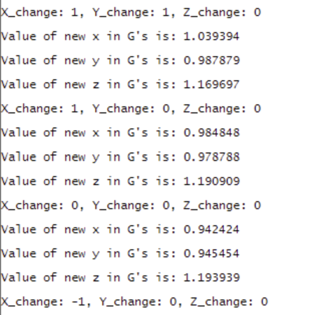
The NeoPixel WS2812 LED ring is controlled by a digital pin on the ATmega328PB. It will change color depending on ADXL335 XYZ state changes.
- ZigBee - XBEE S2C module:
First we configured the Zigbee modules using the XTCU software to give them the same PAN ID: 3332 (in our case). Both Zigbee were configured for no parity, 2 stop bits, 8 bit data.
The sender node: (Serial Number and Destination Address Config):
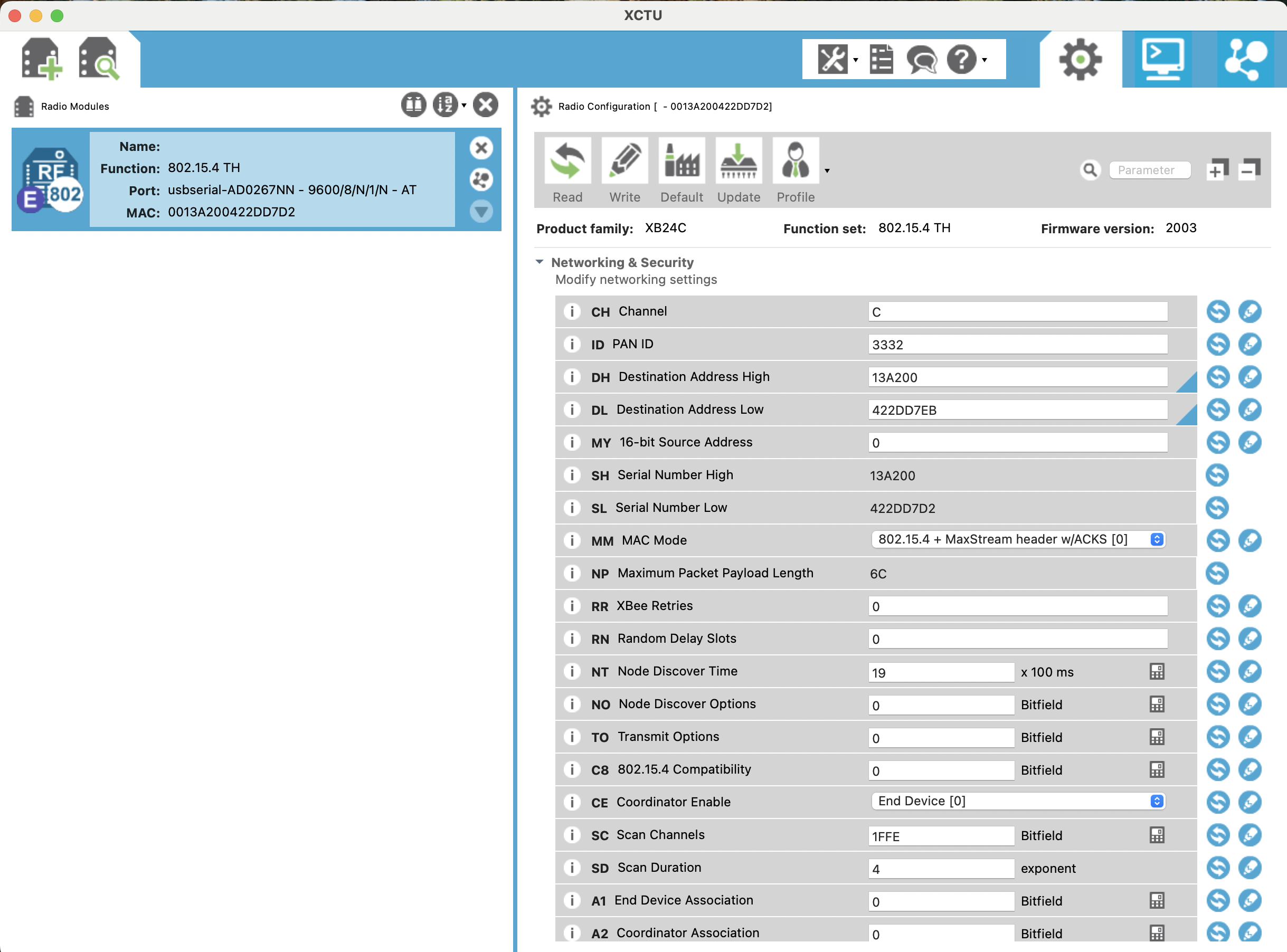
The Destination address (DL, DH) is changed to match Serial address of the receiver.
The Receiver Hub: (Serial Number and Destination Address Config):
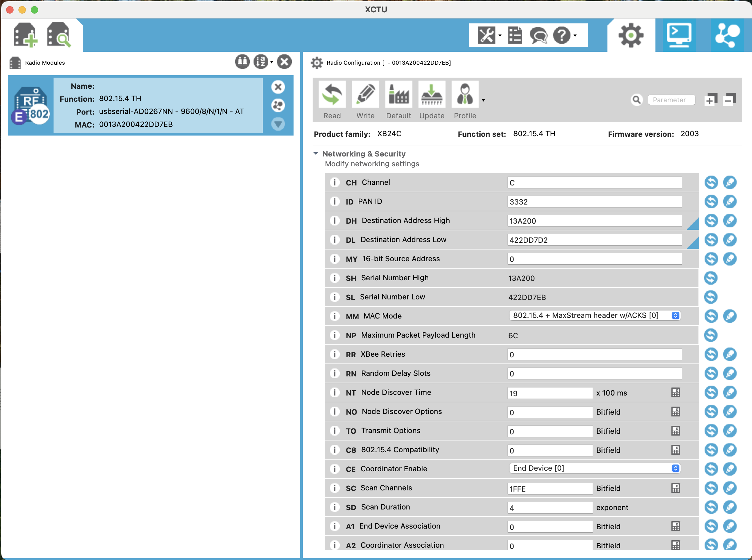
The Destination address (DL, DH) is changed to match Serial address of the sender.
After configuration of the ZigBees a library utilizing USART0 (UART) protocol was made to help send data wirelessly from one Atmega328P to another.
zigbee.H
#ifndef ZIGBEE_H
#define	ZIGBEE_H

#include <avr/io.h>

void UART_Zigbee_init(int prescale);

void UART_Zigbee_send(unsigned char data);

void UART_Zigbee_putstring(char *StringPtr);

unsigned char UART_Zigbee_receive(void);

#endif	/* ZIGBEE_H */
zigbee.c:
#include <avr/io.h>

void UART_Zigbee_init(int prescale)
{
    UBRR0H = (unsigned char)(prescale >> 8);
    UBRR0L = (unsigned char)prescale;
    UCSR0B = (1 << RXEN0) | (1 << TXEN0);                // Enable RX and TX
    UCSR0C = (1 << UCSZ01) | (1 << UCSZ00);
}

void UART_Zigbee_send(unsigned char data)
{
    while (!(UCSR0A & (1 << UDRE0)));                    // Wait for empty buffer
    UDR0 = data;                                         // Send data
}

void UART_Zigbee_putstring(char *StringPtr)
{
    while (*StringPtr)
    {
        UART_Zigbee_send(*StringPtr++);
    }
}

unsigned char UART_Zigbee_receive(void)
{
    while (!(UCSR0A & (1 << RXC0)));                     // Wait for data
    return UDR0;
}
Sender main.c:
#define F_CPU 16000000UL
#define BAUD 9600
#define BAUD_PRESCALER ((F_CPU / (16UL * BAUD)) - 1)

#include <util/delay.h>
#include <avr/io.h>
#include <stdbool.h>
#include <stdio.h>
#include "UART.h"
#include "zigbee.h"


bool flag = true;

int main(void)
{
   UART_Zigbee_init(BAUD_PRESCALER);    // Initialize USART1 for Zigbee
   UART_Debug_init(BAUD_PRESCALER);     // Initialize USART0 for debugging

   unsigned char data1 = 'A';    // Example byte to send
   unsigned char data2 = 'B';    // Example byte to send

   while (1)
   {
       // Send one byte of data via Zigbee (USART1)
       if (flag)
       {
           UART_Zigbee_send(data1);

           flag = false;
       }
       else
       {
           UART_Zigbee_send(data2);

           flag = true;
       }

       _delay_ms(200);
   }

   return 0;
}
Receiver main.c:
#define F_CPU 16000000UL
#define BAUD 9600
#define BAUD_PRESCALER ((F_CPU / (16UL * BAUD)) - 1)

#include <util/delay.h>
#include <avr/io.h>
#include <stdbool.h>
#include <stdio.h>
#include "UART.h"
#include "zigbee.h"

#define LED PC3

int main(void)
{
    UART_Zigbee_init(BAUD_PRESCALER);    // Initialize USART1 for Zigbee
    UART_Debug_init(BAUD_PRESCALER);     // Initialize USART0 for debugging

    uint8_t received_data;

    DDRC |= (1 << PC3);

    PORTC &= ~(1 << LED);

    while (1)
    {
        // Receive one byte of data via Zigbee (USART1)
        received_data = UART_Zigbee_receive();
          if( received_data == 'A')
          {
              PORTC |= (1 << LED);

          }
          else if (received_data == 'B')
          {
              PORTC &= ~(1 << LED);

          }
    }

    return 0;
}
These Codes were used to implement proper Zigbee wireless communication.
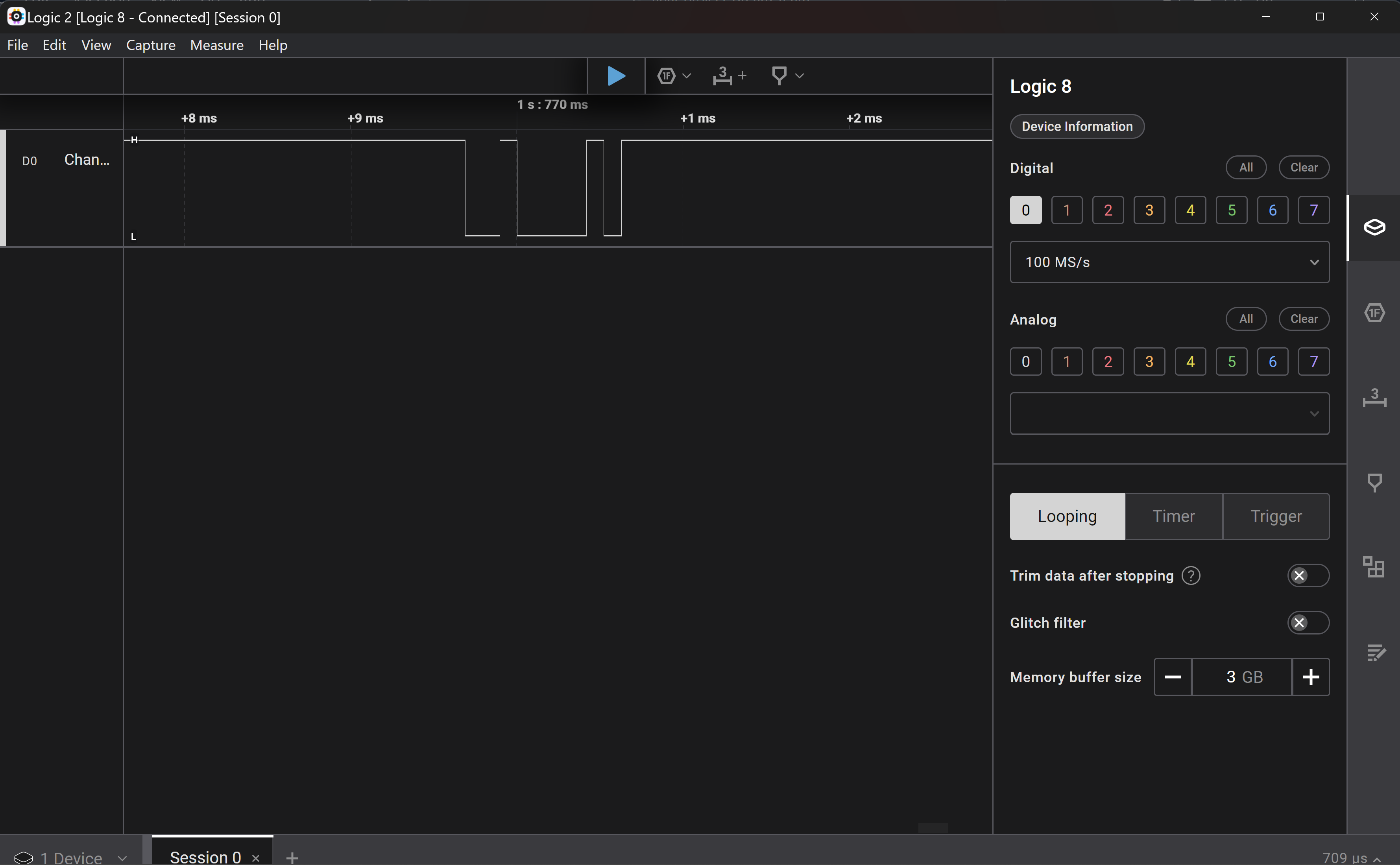
The sender Zigbee sends alternating bytes of values ‘A’ and ‘B’. The receiver interprets these values and wicthes the LED on/off based on the incoming byte.
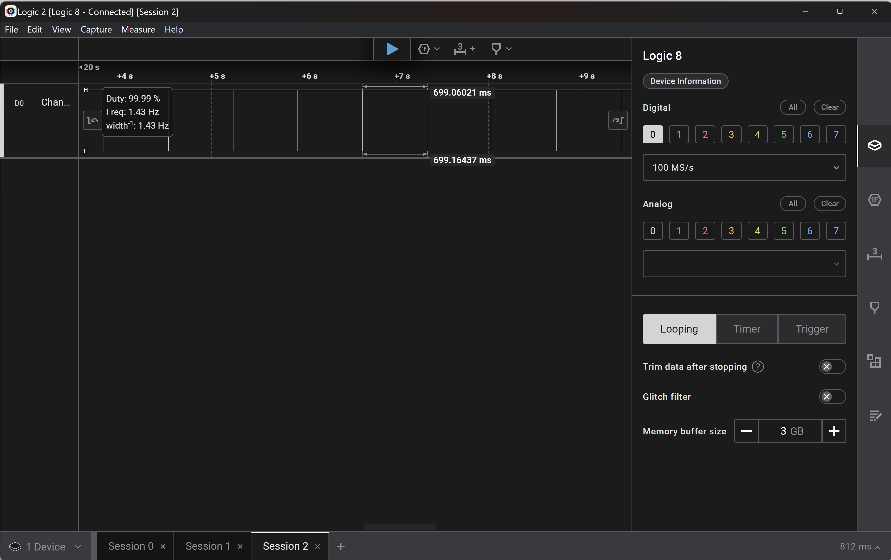
The following video demonstatrates the toggling LED. The sent data can also be printed on the serial monitor as it uses USART0. Further we used a logic analyser to read the sent and received data on the RX/TX pins of the sender and receiver.
- Firmware for Integration of wireless state transmission and modulating the music using MIDI tools:
Hardcoded states looping were transmitted from the transmitter (to emulate ADXL states) to the receiver node.
These states were trasfered to the Atmega communicating with the MIDI device using a 4 wire GPIO bridge that uses bit sequence to validate the states.
This transmitted data was then converted into MIDI mnemonics relating to certail music controls.
TR/RX Data Rate shown on logic analyzer:
3) Have you achieved some or all of your Software Requirements Specification (SRS)?
Acheived:
-
Successfull MIDI control using Atmega and Laptop with Python and UART.
-
Successfull interfacing of IMU with Atmega328PB over I2C.
-
Successfull wireless communcation using Zigbee module interfaced with Atmega328PB over UART.
-
Successfull interfacing of NEOpixel and LED strip using GPIO pins and PWM.
Not Achieved:
-
Unable to interface and establish wireless communcation using nrf24L01 over SPI.
-
Unable to Program USB chip (Mega32U4) to bypass using python and make MIDI interfacing fully in baremetal C.
4) Have you achieved some or all of your Hardware Requirements Specification (HRS)?
Acheived:
-
Complete wireless communication between glove atmega and receiver node.
-
Exploiting 3 DOF from an ADXL335. Hoping to get all 6 by final demo!
-
Utilizing UART and I2C protocol.
-
Utilizing PWM and addressable LEDS for the neopixel.
Not Acheived:
-
Power supply is not isolated and not wireless for the gloves
-
Prop stage with LCD not yet completed will be completed for the final demo.
-
Unable to conigure zigbee on USART1 of the atmega. the data was being received by the Zigbee but not being transmitted to the Atmega over USART1.
5) Show how you collected data and the outcomes.
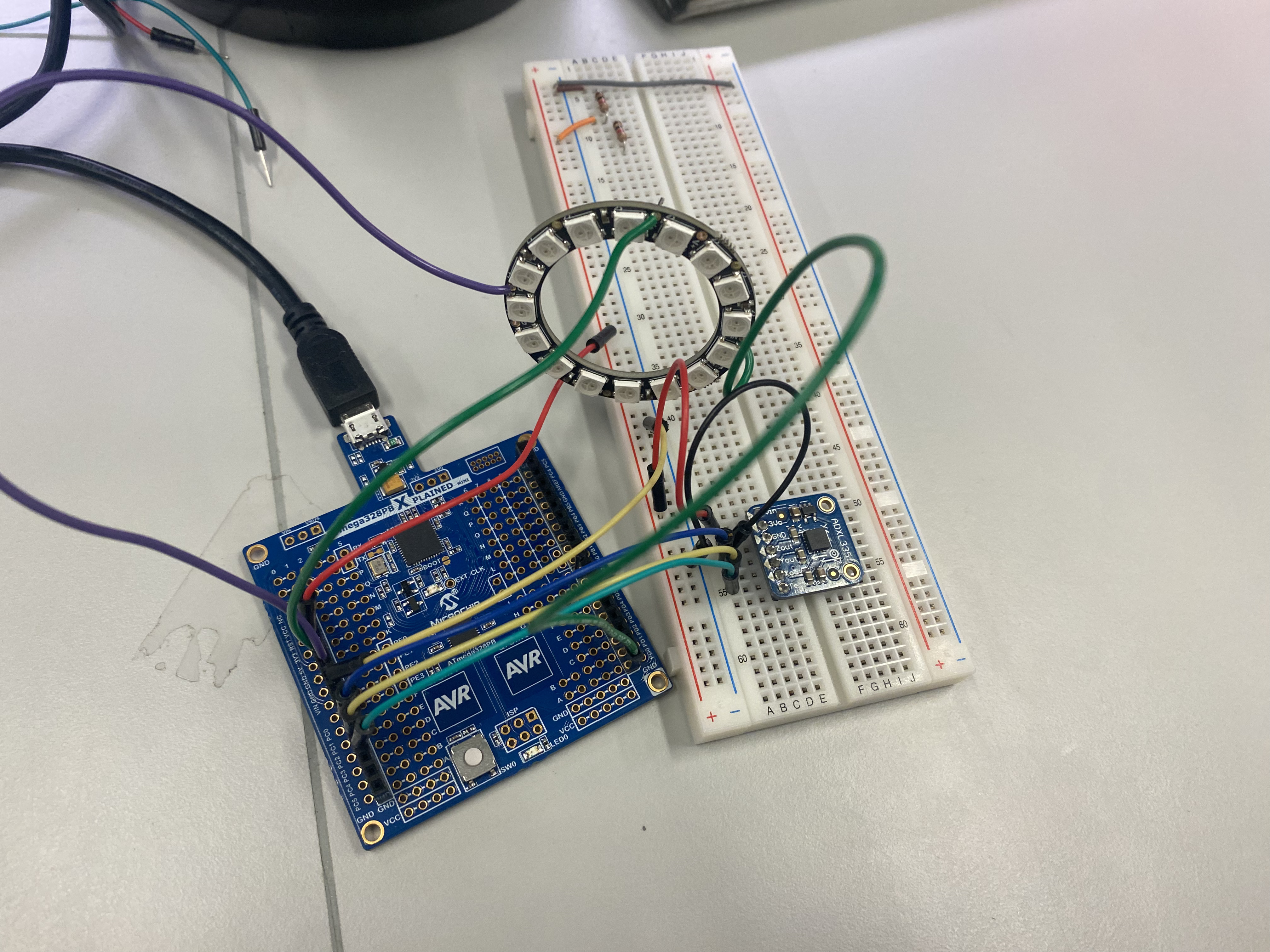
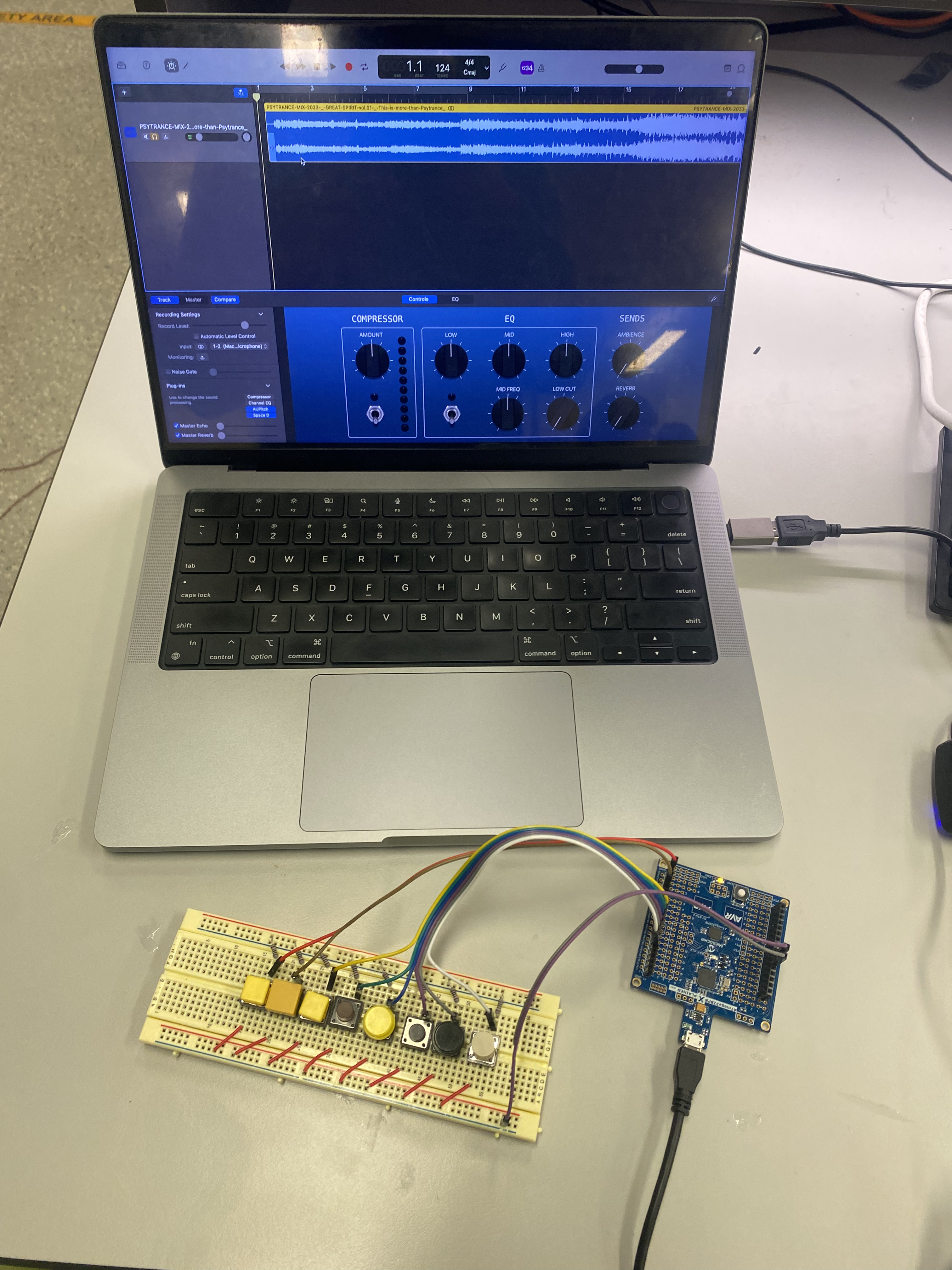
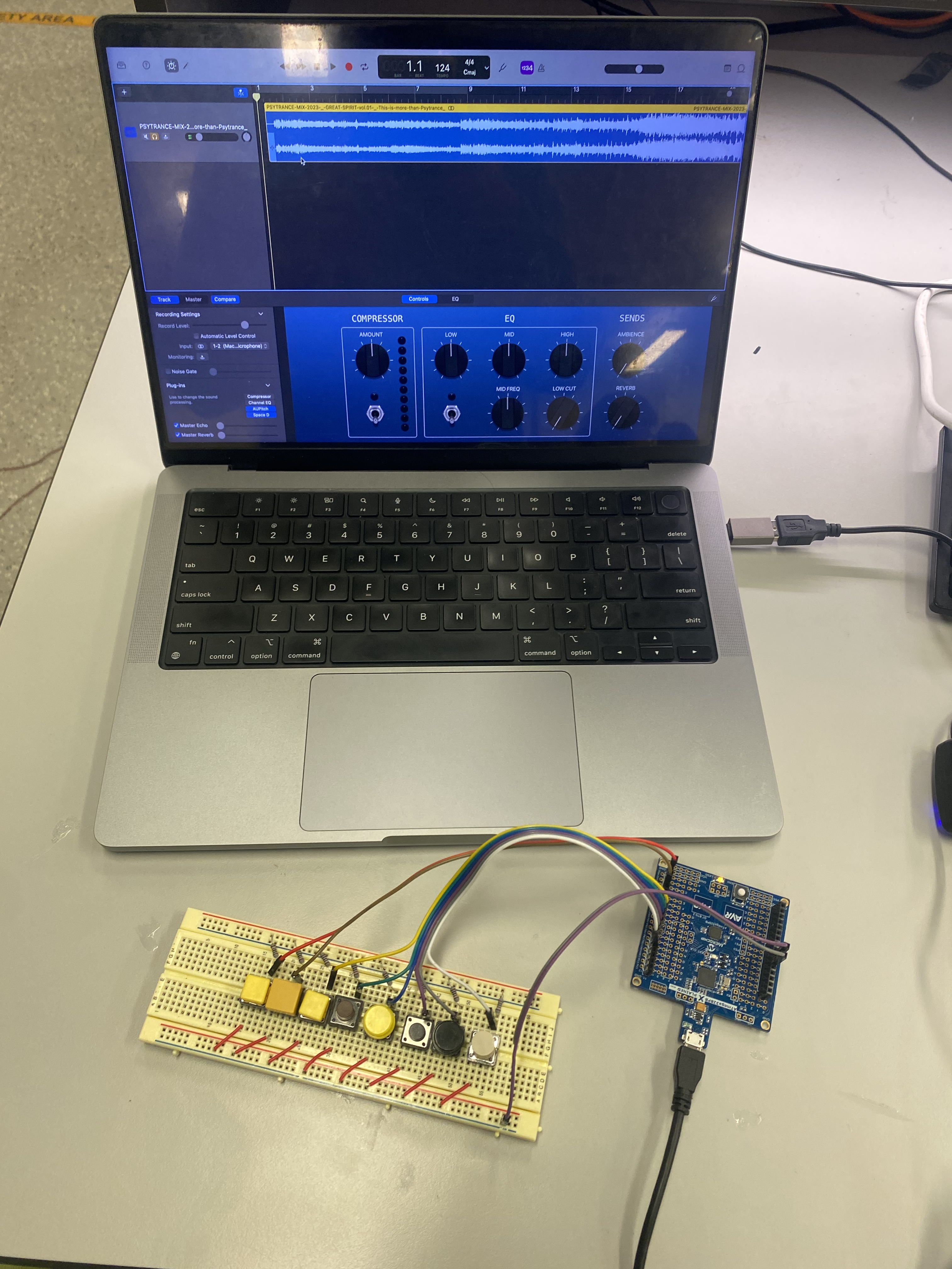
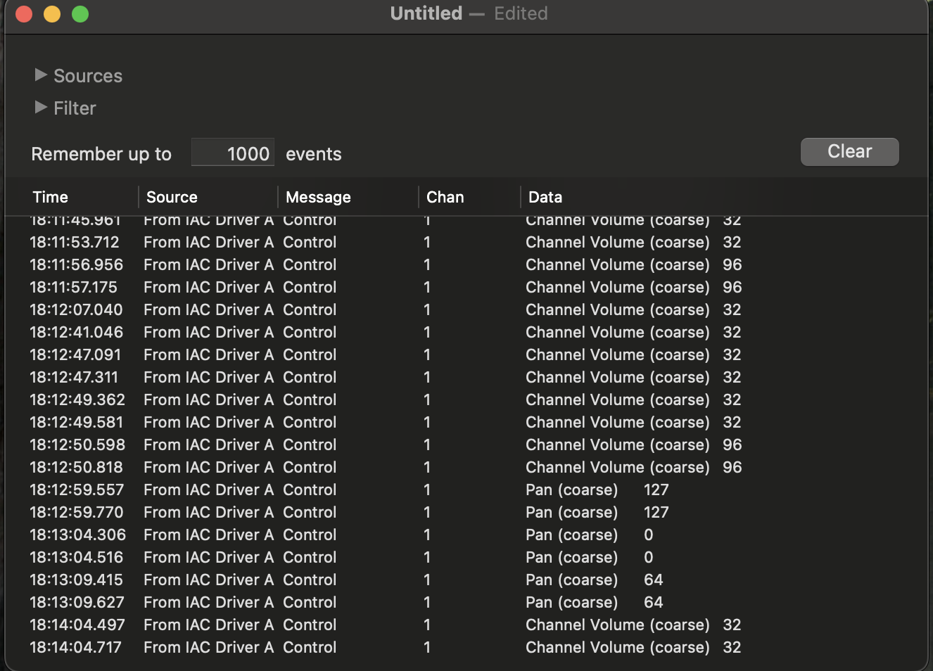
We are using 8 different states to change the configuration of sound in the Garadgeband workstation, out based on the input states out ATMega send a MIDI (Musical Instrument Digital Interface) command over the UART protocol to the a Python bridge script running on our Laptop which forward this to the Gradgeband to manipulate the audio to give us DJ. We are also monitoring these MIDI command using MIDI Monitor, to verify the correct operation.
We tried programming the USB chip in ATMega328PB to act as a standalone MIDI controlled but the after multiple implementation and discussion with TA’s we concluded that USB chip is flashed and firmware update wire is Cut to prevent further change in the USB controller, Hence we leverage the MIDI Bridge to overcome this gap.
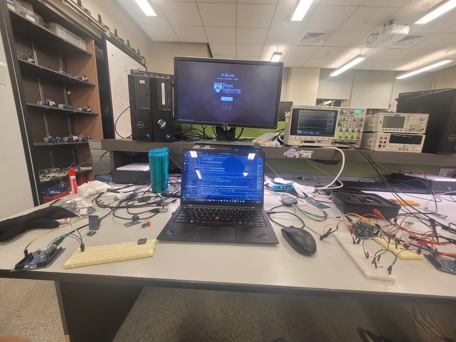
Zigbee communication test


6) Show off the remaining elements that will make your project whole: mechanical casework, supporting graphical user interface (GUI), web portal, etc.
Integration of the input and actuator sub-system present at the glove, and successfully being able to send the IMU data over wireless communication.
Wring and clearing up the cable management while reducing the form factor to make everything fit on one glove.
Testing codes for the completed project and looking for all upper/lower limits of data ranges.
Documenting each and every interface and library created along with schematics.
Final Expected System diagram:

1) Demo your device
Garage band demo: https://drive.google.com/file/d/1ITvoW6TBajpoYM1fCPO_hUhhKps99rsm/view?usp=sharing
NeoPixel WS22812 LED ring: https://drive.google.com/file/d/1u8GsDy0wE-SAH6kXk1ogv6VY79Owm-f3/view?usp=sharing
Zigbee test Demo: https://drive.google.com/file/d/1_yGVNGBudKrngQBVt4NNvV8jsyJfRqOu/view?usp=drive_link
Zigbee + MIDI integration demo: https://drive.google.com/file/d/1a6MHJp4Mq8Fa0_69L3BxjQOlwaN_MNdY/view?usp=drive_link
8) What is the riskiest part remaining of your project?
The riskiest part of out project remaining:
-
Integration of IMU, Zigbee and Neopixel on the same Atmega. All these interafaces utilize different kinds of communication protocol and have been currently implemented using polling.
-
Managing the form factor of the prototype on a glove.
a. How do you plan to de-risk this? We are looking into multiple communication standards and ways to make them fit together. Utilization of interrupts will be key in integrating all the parts on the atmega and will help reduce the polling load.
9) What questions or help do you need from the teaching team?
Our NRF is not properly communicating, we did discusses this with the teaching staffs and also used debugging methods. We have moved to Zigbee Xbee S2C to cover the wireless communication without sacrifising any functionality of out project. Further, we would need help to understand why the atmega wasnt able to receive any data on the
Sprint review #2
ADXL345 Update :
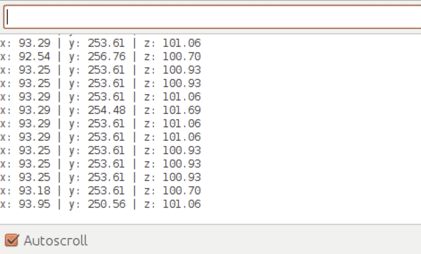 We have finished I2C communication between the ADXL345 and our microcontroller. Currently this data is displayed using UART protocol. The data is represented as XYZ acceleration and mapped to state variables to determine the intensity of movements.
MIDI Update : Test Setup
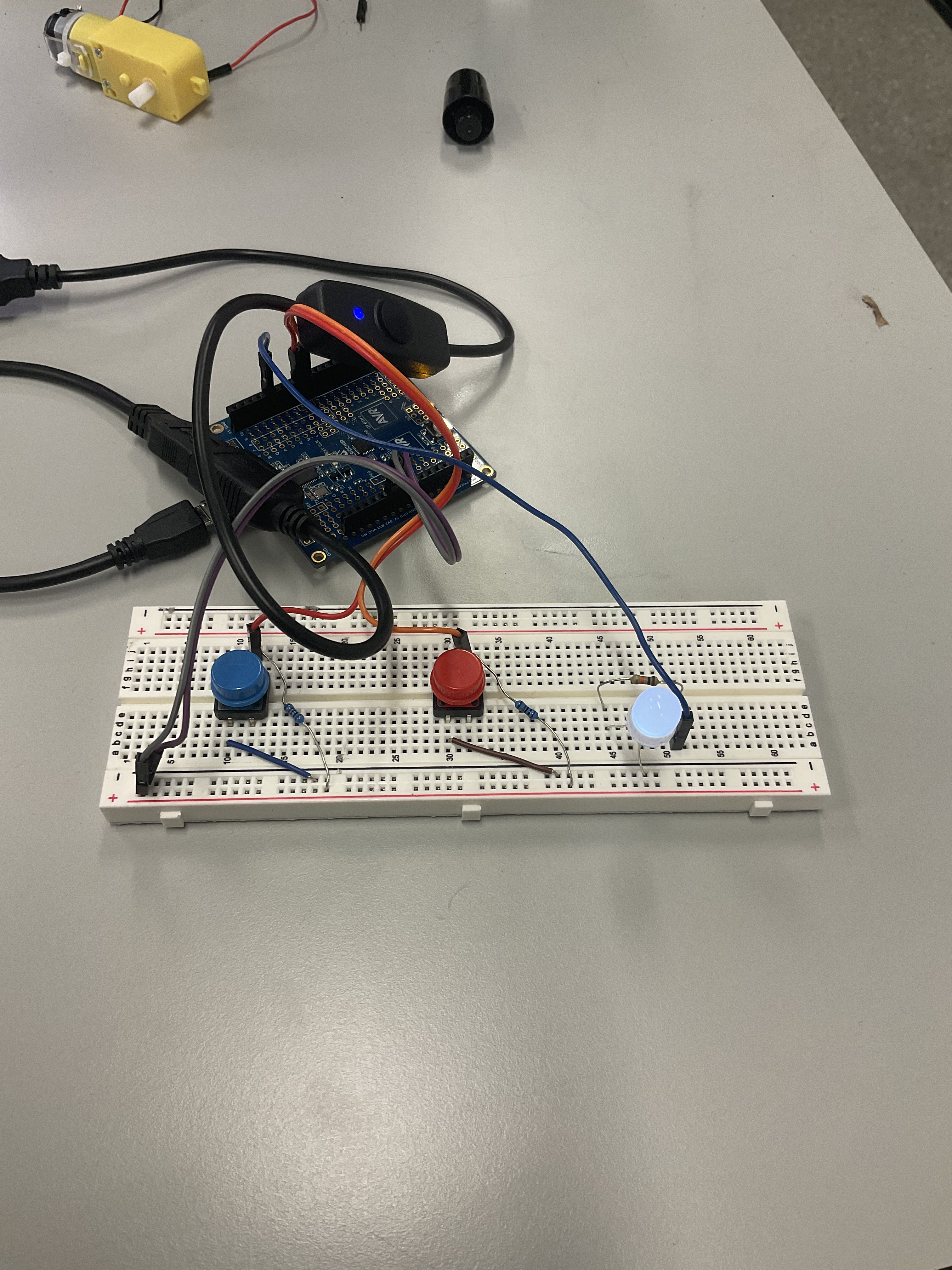
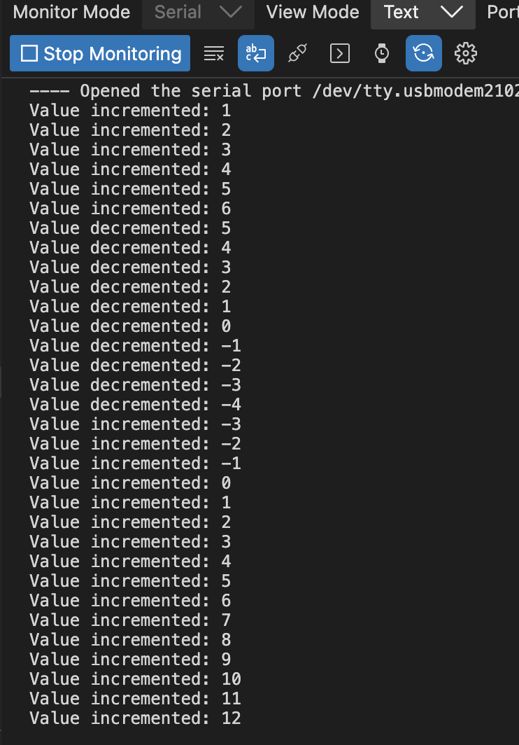
Code </br> We have created a serial input to test the MIDI controller data input, we are working on the development of MIDI controller using the ATMega32PB. The current system is handling the interaction using the UART protocol to handle the date transfer.
RF transmission Setup and test:
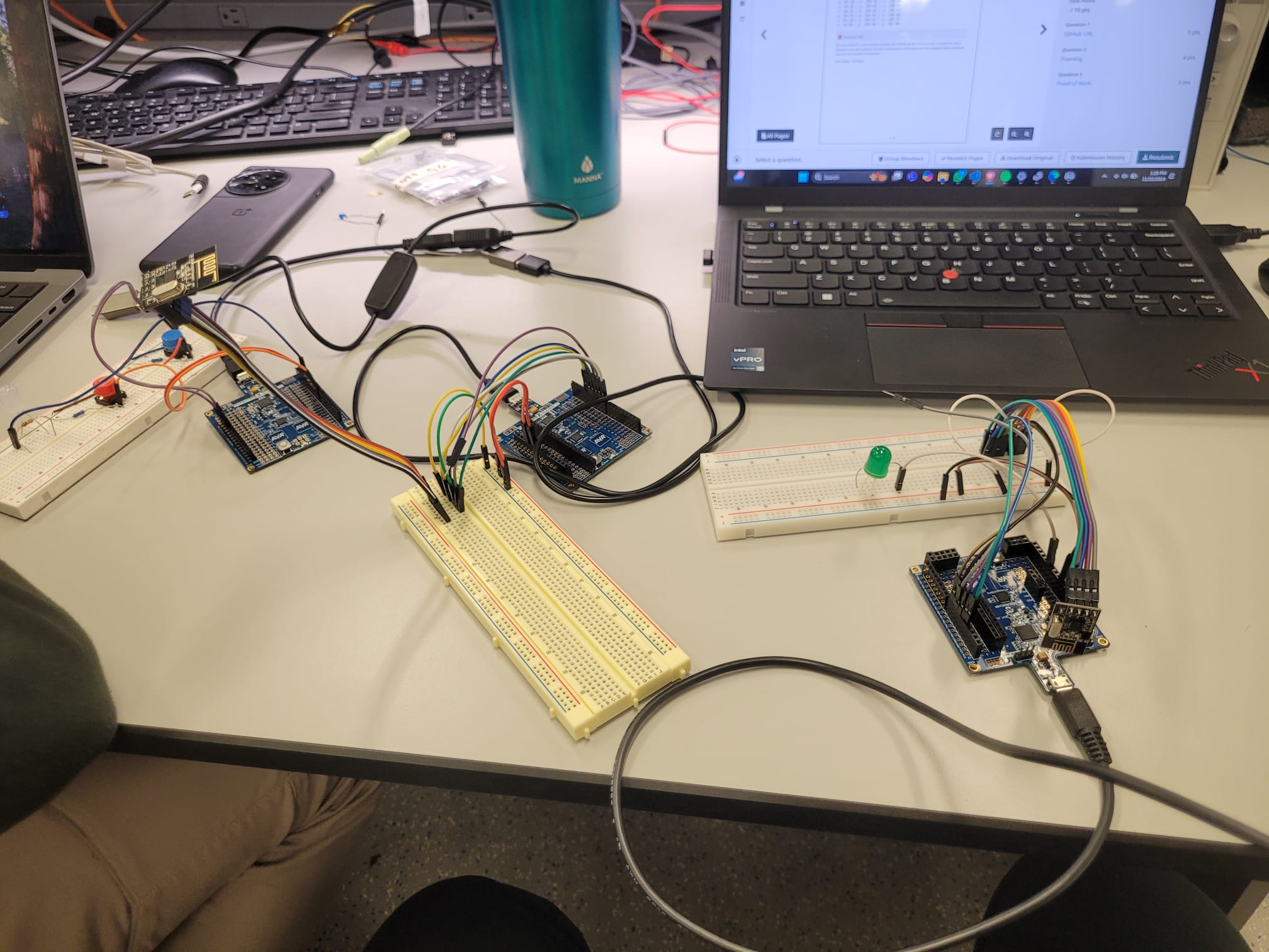
Library and interfacing code for RF is being implemented to get successful wireless data transmission. Currently, no successful data transmission has been noted.
Sprint review #1
Current state of project
1. Currently, we've implemented I2C communication between the ADXL345 aceelerometer and the Atmega328PB. The accelerometer successfully streams XYZ position of the user to the serial monitor via UART. We are testing this component individually before integrating with the other parts of our system. 2. Additionally we've implemented SPI communication and made a library for SPI commination. Further, we've started work on how the wireless communication will be conducted using the NRF24L01 RF module. Currently trying to create a library for the NRF module that would be able leverage the above created library for SPI communication. 3. We are testing the incorporation of ATmega signal with different applications which can process the data in to desired output (Volume Up, Volume Down). We have tested dummy signals for this.
Last week’s progress
Last week, we implemented I2C communication between the ADXL345 aceelerometer and the Atmega328PB. The accelerometer successfully streams XYZ position to the user and these values are displayed over the serial monitor via UART. Further, we were able identify what protocol we would like to use for our wireless communication (between BLE and RF). Upon deciding that we have started writing necesaary codes required to interface the RF module.
Next week’s plan
Next week, we will working on doing analysis of the 6 axis ADXL345 data and encode these accelerometer readings into state values. The XYZ position states will be normalized from 0-1 with the default XYZ position representing 0.5. Further, upon attaining correct functionality and data transmission of the SPI leverage NRF module we aim to move on to integrating this part of our project so that we can wirelessly send the ADXL345 values over RF communication.
Sprint review trial
Current state of project
The project is in the component testing and interfacing phase, with key parts like NeoPixel rings, IMUs, and accelerometers identified and partly ordered. The team has finalized the bill of materials and acquired most components, prioritizing testing before committing to additional orders. They are evaluating different accelerometers for 6-axis data extraction and gesture recognition and experimenting with DJ software for controlling audio features like pitch, volume, and tempo. Wireless communication options are also being tested, particularly the Nordic nRF24L01 module, to establish reliable data transfer with the ATmega328PB. The focus remains on testing individual components separately to ensure compatibility and functionality before integrating them in the upcoming stages.
Last week’s progress
Last week, we identified all key components needed for our project and finalized the bill of materials. We ordered two NeoPixel rings, having acquired most other components from Detkin, and shared the BOM list with the team. We are also testing several IMUs to determine the best fit for our application and plan to finalize and place an order for the selected IMU by next week. In a meeting with our project managers, Chen Chen and Nick, we refined our system block diagram and identified data transmission rates as a potential bottleneck due to the ATMEGA32PB’s limited memory. To improve form factor and performance, we discussed using a smaller MCU on the glove and potentially switching to the Nordic nRF24L01 for wireless communication instead of the HC05 Bluetooth module.
Next week’s plan
Next week, we plan to test various accelerometers by interfacing them with the ATmega328PB to extract 6-axis data and perform basic gesture recognition. Additionally, we will explore different DJ software options and begin working on interfacing with them to control speaker pitch, volume, and tempo. For wireless communication, we will focus on connecting the Nordic nRF24L01 module with the ATmega328PB to ensure smooth data transfer. Our goal is to individually test each of these components to confirm their functionality. By doing so, we aim to identify and address any issues early on. This approach will set a strong foundation for integrating the components in future weeks.
### Current state of project ### Last week's progress ### Next week's plan ## Final Project Proposal ### 1. Abstract
In a few sentences, describe your final project. This abstract will be used as the description in the evaluation survey forms.
The DJ Gloves project introduces an innovative way for users to control and customize live music through simple hand gestures. By equipping concert-goers or DJs with gloves embedded with motion sensors, this project enables seamless, intuitive control over music settings such as volume, tempo, and pitch, providing a personalized listening experience. The concept leverages wireless technology to allow users to adjust music in real-time from anywhere in a venue, revolutionizing the interaction between people and sound.
### 2. MotivationWhat is the problem that you are trying to solve? Why is this project interesting? What is the intended purpose?
Problem: In many live music settings—such as concerts, festivals, or parties—the music experience is standardized for everyone in the audience. Factors like volume, tempo, and pitch may not suit individual preferences, and in large venues, adjusting these settings can be challenging without interfering with others' experiences. DJs and DJing in general has a very confusing and complicated bar of entry which often limited physical movements especially keeping their hands busy, limiting their creative expression.
Purpose and Inspiration: This project is inspired by the concept of a conductor leading an orchestra with hand gestures, creating a flow that resonates with the audience. Similarly, the DJ Gloves project seeks to give users, whether they are audience members or DJs themselves, the power to interact with and adjust music through hand gestures. By translating natural hand movements into music control signals, the DJ Gloves empower users to personalize and enhance their musical experience seamlessly, making concerts and events more engaging and immersive. Further, the input methodology being implemented has a general purpose of creating a device that allows a user control over any bluetooth enabled device in a more interactive and intuitive way. Ex: RC cars, light, swarm robots etc.
### 3. GoalsThese are to help guide and direct your progress.
The primary objectives of the DJ Gloves project are as follows:
- Develop Gloves Equipped with IMUs: Design and construct two gloves, each integrated with Inertial Measurement Units (IMUs) to accurately capture user hand movements. These sensors will detect changes in acceleration and orientation, providing data about the direction and intensity of motions.
- Detect and Process Motion Data: Implement algorithms to interpret IMU data, identifying specific gestures that correspond to different music control commands. For instance, raising a hand may increase volume, while rotating it may adjust the tempo or pitch. The goal is to ensure seamless, real-time detection and response.
- Integrate with DJ Software: Establish communication between the gloves and DJ software (such as Mixxx or other open-source platforms) to translate hand gestures into music controls. Through wireless communication, data from the gloves will adjust music parameters like volume, tempo, and pitch, allowing for a highly interactive DJing experience.
- Enhance Visual and Audio Feedback: Integrate LEDs on the gloves that light up based on motion intensity, creating visual feedback that enhances the concert atmosphere. Additionally, the gloves will control external speakers and possibly other devices to create a cohesive audiovisual experience.
Each goal contributes to the overall vision of transforming the way music is experienced in live settings by enabling users to interact directly with sound through intuitive hand gestures.
### 4. System Block DiagramThese are to help guide and direct our progress.
The above block diagram can be best explained in 4 stages of how the proposed embedded system works: 1. The input stage: a. The ADXL345 sensor (Inertial movement unit): capable of measuring 6 degrees of freedom. b. Bluetooth Module: Enables wireless transfer of IMU measurement to the ATmega32PB. 1. Proceeding unit (Microcontroller): a. Here the data sent BLE is mapped to finite states. This is done to de-couple or abstract the input from the output or the actuation. b. The microcontroller also provides the hardware to generate PWM, manage interrupts to have proper functionality of the actuators. 2. Laptop: a. Manages the DJ software that changes the tempo, amplitude and modularity of the sound/song being played. 3. The output stage: a. Speakers: Play the modulated sound/song. b. LED strips: The light gradient and intensity changes in accordance with the intensity and tempo of the song.Present on the prop stage and both gloves. c. LCD Screen: A LCD screen with a custom library (something similar to a old school windows media player) graphics which also changes in accordance to the input state.
GLOVE
Provides a easy to use wearable light-weight device that enables bluetooth input based on the movement and orientation of the users hand. Making it a more generalized and intuitive input method.
ADXL345 IMU (Sensor)
This is a 3-axis accelerometer (IMU) used to detect hand motion and orientation. The IMU communicates with the Bluetooth module using either SPI or I2C communication protocols to transfer data. It captures data related to acceleration and orientation, which helps in identifying the gestures performed by the user.
Bluetooth Module
The Bluetooth module transmits the IMU data wirelessly to the central microcontroller (ATmega32PB). This module ensures the glove can communicate in real-time with the main system without the need for physical connections. Each glove has its own Bluetooth module, allowing two-way communication between the gloves and the central system.
LED Strips on the Glove
The LED strips are mounted on each glove to provide visual feedback. The LEDs light up based on user actions, adding a visual element that syncs with the music. The LED control is influenced by the motion data collected by the IMU, creating an interactive experience as the LEDs respond to gestures.
ATmega32PB Microcontroller
The ATmega32PB serves as the main processing unit of the system. It receives data from the Bluetooth modules in each glove, interprets the motion data, and translates it into commands for the DJ software and connected devices. The microcontroller handles Timers, PWM (Pulse Width Modulation), Interrupts, and Duty Cycle controls for managing connected components.
"Prop Stage" LCD Screen & LEDs (Actuators)
The Prop Stage includes an LCD screen and additional LED lights that serve as visual indicators synchronized with the music and 3D stage if time permits. The ATmega32PB controls these actuators by adjusting brightness, colors, or patterns based on the music or gestures.
DJ Software Interface
The DJ software, running on a computer, receives data from the ATmega32PB to adjust music parameters such as tempo, volume, and pitch. This data originates from the gloves and is processed by the microcontroller to control the audio output, providing an interactive DJ experience.
Speaker (Actuator)
The speaker is the primary audio output device. It plays music from the DJ software and responds to changes made by the glove movements. The audio output is influenced by the real-time data from the IMU sensors, allowing users to control the tempo, volume, and other audio effects through gestures.
### 5. Design SketchesThese are to help guide and direct our progress.
 Gloves with IMU and LED Strip: Each glove is equipped with an Inertial Measurement Unit (IMU) and an LED strip. The IMU sensors detect the movement and orientation of the user’s hands, capturing data that represents the position and orientation of the hand. These coordinates and axis's correspond to specific music control actions, like adjusting volume or tempo. The LED strips on the gloves provide visual feedback based on motion, creating an interactive and immersive audio-visual experience. IMU Data Transmission via BLE: The data from the IMUs on each glove is sent wirelessly via Bluetooth Low Energy (BLE) to the central microcontroller (an ATmega32-based system). BLE is used for its low power consumption, ensuring that the gloves remain functional for longer periods without frequent recharging. Microcontroller Processing: The ATmega32 microcontroller processes the incoming IMU data. It interprets the gestures and translates them into music control commands. For example, certain hand movements might adjust the music's tempo, volume, or pitch. Additionally, the microcontroller handles the LED and LCD inputs to display relevant information or visual effects, enhancing the user experience. DJ Software Interface: The microcontroller sends the processed data to the DJ software on a connected laptop, where it is interpreted as commands to control the music. This DJ software (such as Mixxx or another open-source platform) then adjusts the music output based on the user’s gestures, allowing the user to manipulate music settings wirelessly and interactively. Output to Speaker: The modified audio output from the DJ software is sent to the speakers, allowing the audience to hear the real-time adjustments made by the user. This can create a dynamic and engaging musical performance where the user can control various aspects of the sound with intuitive gestures. LED and LCD Feedback: The system includes additional LEDs and possibly an LCD display that provide real-time feedback to the user and audience. This feedback could include visualizations of the music's rhythm or beat, which change in sync with the music, enhancing the concert or performance atmosphere.
### 6. Software Requirements Specification (SRS)Formulate key software requirements here. They must be testable! See the Final Project Manual Appendix for examples.
6 Software Requirements Specification
6.1 Overview
The DJ Glove project is an embedded system allowing users to control DJ software and produce music through hand gestures. By utilizing an IMU sensor to detect motion and a Bluetooth module to transmit data, the glove will control various audio effects, such as pitch, volume, and filter adjustments, via open-source DJ software like Mixxx. The system includes custom software algorithms for gesture recognition, communication, and seamless integration with DJ software.
6.2 Users
The primary users for the DJ Glove are:
- DJ Enthusiasts - Individuals interested in enhancing their music control experience with innovative, hands-free control methods.
- Performers and Musicians - Artists who want to add a visual, interactive element to their performances.
- Developers - Those interested in exploring or modifying the open-source code for further customization and experimentation.
6.3 Definitions, Abbreviations
- DJ: Disk Jockey
- IMU: Inertial Measurement Unit, used to measure acceleration and rotation.
- HC-05: A Bluetooth module used for wireless data transmission.
- MPLAB: Microchip’s Integrated Development Environment (IDE) for developing embedded software.
- I2C: Inter-Integrated Circuit, a communication protocol for the LCD display.
- Mixxx: Open-source DJ software that supports MIDI input for music control.
6.4 Functionality
- SRS 01 – The IMU 3-axis acceleration will be measured with 16-bit depth every 100 milliseconds ±10 milliseconds.
- SRS 02 – The software shall support Bluetooth communication between the glove and a paired device for transmitting IMU data in real-time.
- SRS 03 – The software shall interface with Mixxx DJ software via MIDI signals to control audio effects.
- SRS 04 – The system shall use gesture recognition to control audio features such as pitch, volume, and filter based on IMU data.
- SRS 05 – The software shall visualize glove orientation and movement on the LCD screen with a refresh rate of 10 frames per second.
- SRS 06 – LED strips on the glove shall respond to gestures and audio cues (e.g., brightness increases with louder volume).
Revisiting SRS at the End of Our Project
- SRS 01 – We successfully interfaced a 3-axis IMU that provides ADC data, and we sampled this data at regular intervals.
- SRS 02 – We developed firmware to support wireless communication using the Zigbee X2C module, which operates on UART to transmit the states mapped to IMU data in real-time. We pivoted from using a Bluetooth sensor to a Zigbee module.
- SRS 03 – The firmware we developed can send MIDI signals to any software compatible with MIDI. Additionally, we implemented a Python bridge to accept MIDI control signals over UART from an ATmega microcontroller. In our final implementation, we used GarageBand instead of Mixxx DJ software.
- SRS 04 – We successfully deployed firmware capable of changing audio modalities in GarageBand based on hand orientation and gestures.
- SRS 05 – We interfaced four LCD screens over SPI that displayed real-time changes in the audio modalities occurring in the music.
- SRS 06 – Using our firmware, we successfully utilized the Neopixel LED ring on the glove to change colors according to the hand's gestures and orientation.
Formulate key software requirements here. They must be testable! See the Final Project Manual Appendix for examples.
7 Hardware Requirements Specification
7.1 Overview
The DJ Glove hardware is built around the ATmega328P microcontroller, designed to process IMU data for gesture recognition and transmit information wirelessly to DJ software via Bluetooth. Additional components, such as an LCD display and LED strips, provide visual feedback, while a speaker generates audio cues for user feedback.
7.2 Definitions, Abbreviations
- ATmega328P: A microcontroller used as the main processing unit.
- LCD: Liquid Crystal Display, used to show visual feedback on gestures or system status.
- IMU: Inertial Measurement Unit, providing acceleration and rotational data.
- LED: Light Emitting Diode, used for visual feedback in response to audio or gestures.
7.3 Functionality
- HRS 01 – Project shall be based on the ATmega328P microcontroller.
- HRS 02 – An IMU sensor (such as MPU6050) shall detect hand orientation and gestures, with a sampling rate of 10Hz for responsive performance.
- HRS 03 – A 160x128 LCD display shall be used for displaying control information, connected via SPI.
- HRS 04 – A speaker shall emit audio cues based on specific gestures or actions, such as feedback for volume control.
- HRS 05 – LED strips shall change colors or brightness in response to gesture commands or music dynamics.
- HRS 06 – The HC-05 Bluetooth module shall enable real-time wireless communication with the connected device.
Revisiting HRS at the End of Our Project
- HRS 01 – We used four ATmega328PB microcontrollers in total: one on each glove and two inside the stage.
- HRS 02 – We utilized an ADXL335 sensor to detect gesture and orientation changes, leveraging ADC and interrupts for accurate data acquisition.
- HRS 03 – We successfully designed a circuit to run four LCD screens over a single SPI line and arranged them in an orientation to effectively create a large screen effect.
- HRS 04 – We used the laptop's speakers to play music and demonstrate the changes in audio modalities.
- HRS 05 – We fully controlled the color sequencing, brightness, and intensity of the LED strip and the Neopixel rings by utilizing timers.
- HRS 06 – We modified this hardware requirement by using an XBEE S2C (Zigbee) module to establish real-time wireless communication instead of the Bluetooth HC05 module.
What major components do you need and why? Try to be as specific as possible. Your Hardware & Software Requirements Specifications should inform your component choices. Add links to components.
| Component | Purpose | Link | |-------------------------|--------------------------------------------------------------------------------------------------|-------------------------| | ATmega328PB | Central microcontroller, selected for low power, sufficient IO pins, and compatibility with IDEs | [ATmega328PB Datasheet](https://drive.google.com/file/d/1ZoxflTe-DveEnRnLlahV9N1bbNCXoxui/view) | | MPU6050 IMU | Detects acceleration and rotation, essential for gesture control | [MPU6050 IMU ](https://www.adafruit.com/product/3886) | | HC-05 Bluetooth Module | Wireless communication with computer/mobile DJ software | [HC-05 Bluetooth ](https://components101.com/wireless/hc-05-bluetooth-module) | | 160x128 TFT LCD Display | Provides visual feedback on glove status, gesture, or audio levels | [160x128 TFT LCD ](https://www.adafruit.com/product/358) | | LED Strips | Visual feedback for effects and gestures | [LED Strips {LAB} ](https://www.adafruit.com/product/4278) | | Speaker | Provides audio cues based on gesture recognition events | [Small Speaker {LAB} ](https://www.adafruit.com/product/1314) |
These are just components we have lightly researched more components maybe added and the LCD screen and speaker can be subject to changes based on budgeting and interfacing complexity.
### 9. Final DemoWhat do you expect to achieve by the final demonstration or after milestone 1?
9 Expected Outcomes for Final Demonstration
By the final demonstration, we expect to achieve:
- Gesture Recognition – The glove accurately detects and translates specific gestures into commands within DJ software.
- Visual Feedback – The LCD and LED strips provide real-time feedback on gestures and audio effects.
- Bluetooth Communication – Reliable and responsive Bluetooth connection with DJ software, allowing smooth control of music effects.
- Software Integration – The glove should be able to interface with Mixxx or similar DJ software to control audio parameters like pitch, volume, and filters.
- User-Friendly Interface – Easy-to-understand feedback on both hardware (LEDs and LCD) and software interfaces.
What is your approach to the problem?
The approach to building the DJ Glove involves:
- Research and Feasibility Analysis: Understanding the technical requirements for gesture control, DJ software interfacing, and wireless data transmission.
- Modular Hardware Design: Developing individual modules (Bluetooth, IMU, LCD, LEDs) and integrating them into a compact wearable form.
- Software Development: Writing software to interpret IMU data, recognize gestures, and translate them to MIDI signals or commands compatible with DJ software.
- Testing and Iteration: Testing each component independently, then in integration to ensure reliability and responsiveness.
To measure the effectiveness of the DJ Glove in meeting project goals, we’ll use the following metrics:
- Gesture Recognition Accuracy: Measure how accurately and consistently the glove recognizes specific gestures. Target a 95% accuracy rate for gesture detection.
- Latency: Measure the time delay between gesture execution and corresponding audio effect in the DJ software. Target latency should be less than 100ms.
- Bluetooth Connectivity Stability: Assess the reliability of the Bluetooth connection during continuous use. Target no more than 1 connection drop per hour.
- User Feedback: Gather subjective feedback from users on ease of use and accuracy of control.
Add your slides to the Final Project Proposal slide deck in the Google Drive.
Slides added and Presented!</br> Yay!!!!
## References Fill in your references here as you work on your proposal and final submission. Describe any libraries used here. ## Github Repo Submission Resources You can remove this section if you don't need these references. * [ESE5160 Example Repo Submission](https://github.com/ese5160/example-repository-submission) * [Markdown Guide: Basic Syntax](https://www.markdownguide.org/basic-syntax/) * [Adobe free video to gif converter](https://www.adobe.com/express/feature/video/convert/video-to-gif) * [Curated list of example READMEs](https://github.com/matiassingers/awesome-readme) * [VS Code](https://code.visualstudio.com/) is heavily recommended to develop code and handle Git commits * Code formatting and extension recommendation files come with this repository. * Ctrl+Shift+V will render the README.md (maybe not the images though)