final-project-ohm-sweet-ohm
final-project-skeleton
* Team Name: ohm-sweet-ohm
* Team Members: Venkatesh Komalika & Jyotiraditya
* Github Repository URL:[https://github.com/upenn-embedded/final-project-ohm-sweet-ohm]()
* Github Pages Website URL:[ https://upenn-embedded.github.io/final-project-ohm-sweet-ohm/]()
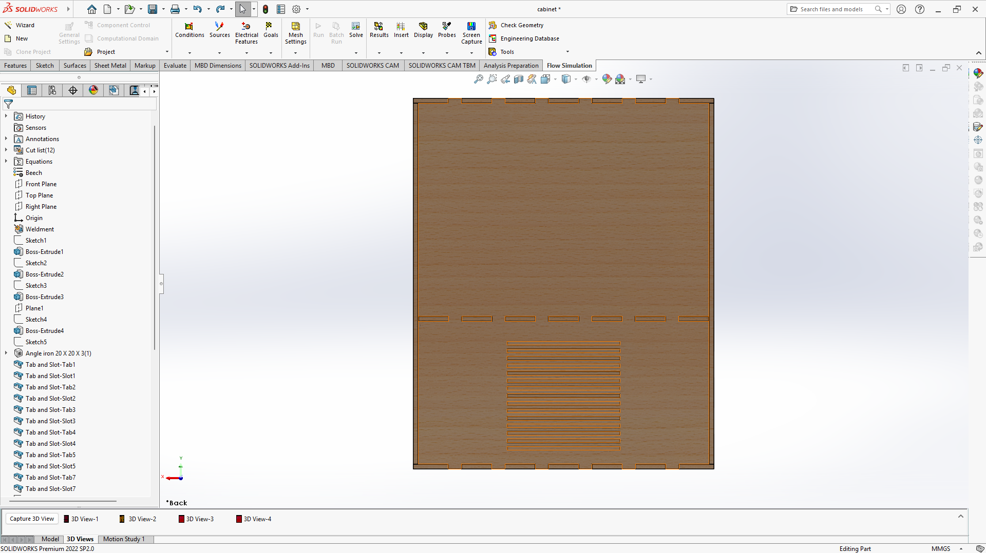
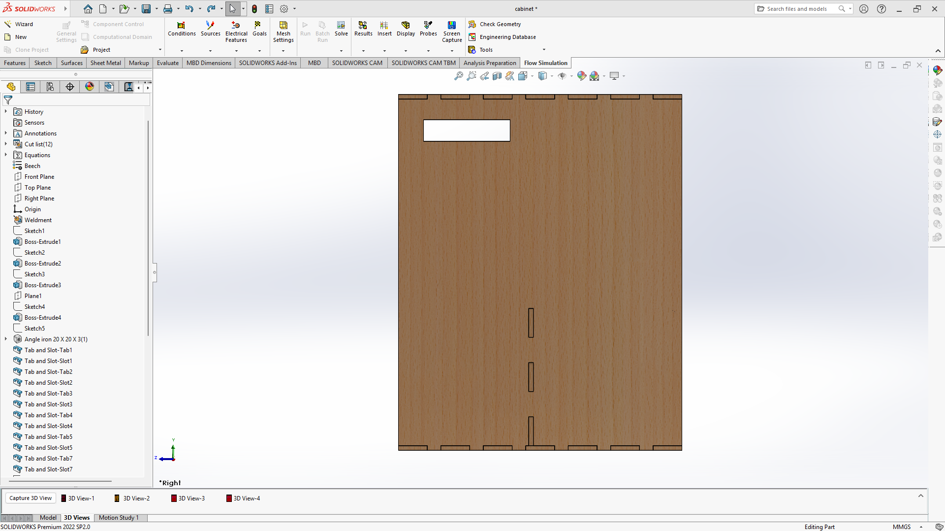
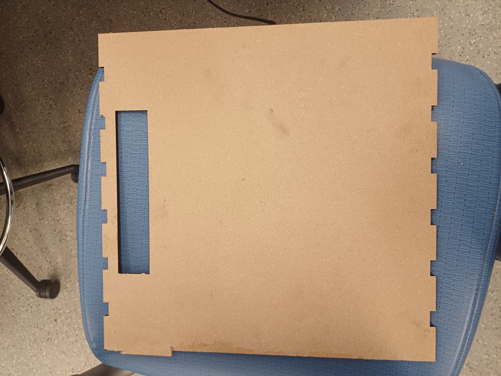
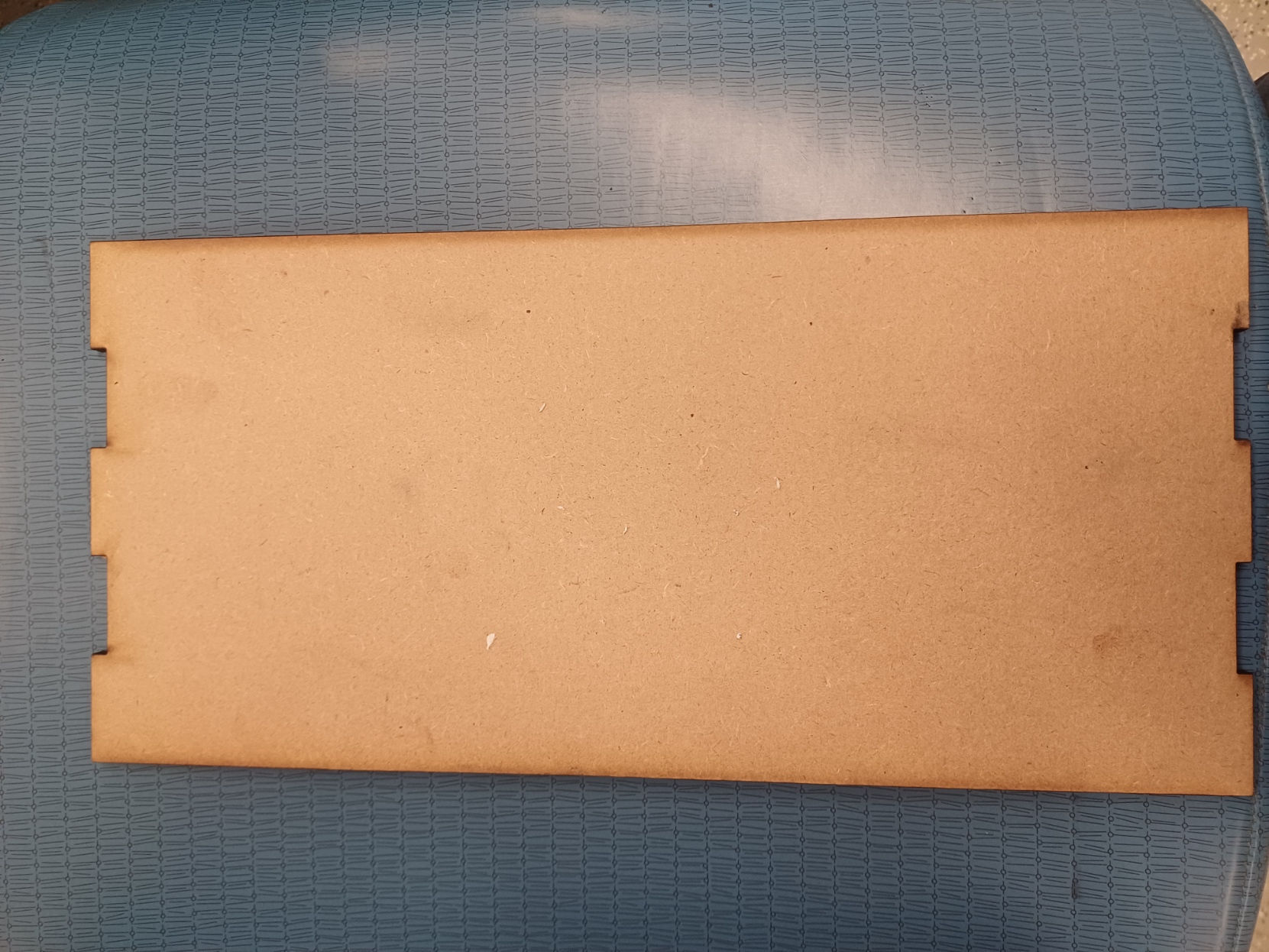
* Description of hardware: The aim of our project is to create a smart shoe dryer especially for the winter season so that users can dry their wet shoes quickly.  In the hardware implemenatation, we have used a temperature and humidity sensor, load cell, heater, relay and fans for implementing our electrical components of our project and we have used MDF, acrylic for the outer frame by laser cutting out the required design and 3D printing was done for designing the platform for the load cell.
Final Project Report
1. Video
Link to the video - https://drive.google.com/file/d/1IilFWwbBmbQqKNDm-Jm01vqyb_RhfAGt/view?usp=sharing
2. Images

3. Results
3.1 Software Requirements Specification (SRS) Results
- SRS 01 – Humidity and temperature sensors will continuously monitor the environment, sending data to the ATmega328pb every second and sending heater temperature every second as well and it’s getting compared every 30 seconds.
- SRS 02 – The weight sensor will measure and update the shoe weight with a precision of 20 grams, and values will be logged every 30 seconds.
- SRS 03 – Relay switches will control the heater and fans based on pre-set temperature thresholds at 30°C , observed every 30 seconds.
- SRS 04 – The display will update every second to show the current temperature, humidity, and weight, as well as the percentage of drying progress.
- SRS 05 – The user can adjust the mode (Automatic, Manual, and Profile mode) via the buttons, with input processing every 30 seconds. (However for the scope for the final demonstration we are focussing on the automatic mode only.) Did you achieve your requirements? Yes. The modes can be selected and the readings for both the sensors are accurate. How did you test? Show proof of work (videos, images, collected data, etc.)
(posted with the hardware)
3.2 Hardware Requirements Specification (HRS) Results
- HRS 01 – The project shall be based on the ATmega328pb microcontroller to control relays, heating coil, fans, and process sensor data.
- HRS 02 – A sensor shall be used to detect the weight of the wet shoe placed in the box. The sensor shall measure weight with an accuracy of 20 grams and send data to the microcontroller.
- HRS 03 – A heater shall be used as the drying element. The coil’s temperature shall be continuously monitored by a temperature sensor to avoid overheating. The system shall shut down the coil if the temperature exceeds a preset limit that 30°C.
- HRS 04 – Two 5V fans shall be used to ensure the circulation of hot air inside the box. The fans shall operate in conjunction with the heating coil to provide an even airflow.
- HRS 05 – An LCD display shall be used to show the real-time weight of the shoe and the estimated drying time. The drying time will be calculated based on the weight and environmental conditions (temperature and humidity).
- HRS 06 – A temperature and humidity sensor shall be used to monitor the humidity and temperature inside the box, ensuring optimal drying conditions are maintained.
- HRS 07 – Relays shall control the power supply to the heating coil and fans, turning them on or off based on the shoe weight, temperature, and humidity readings.
- HRS 08 – A 5V power supply block shall power the microcontrollers and input devices, while a 12V power supply shall be used for the relays and output devices (fans), AC supply for the Heater. Did you achieve your requirements? Yes. How did you test? Show proof of work (videos, images, collected data, etc.) We directly started to work with the components. For the relay we tested with the LEDs to see if the switches would get turned on or not.
We measure the readings every 30 secs but we compare them every 15 mins. After the two/ three consecutive readings are the same, the shoe gets dried and we turn off the heater and the fans.
Proof [To be noted that that the box wasnt covered so the readings for the temperature and humidity are not that different. Also to be noted that the upper limit for the temp sensor was set to be 40 degrees C]
-
Readings before the drying of the shoe:

-
Readings after the drying process is complete :

Three topics
- I2C with weight sensor
- I2C with Humidity and temperature sensor
- Power management
- Interrupts
- Timers
Input devices
- humidity and temperature sebnsor
-
weight sensor
Output devices
- LCD
- Heated chamber
- fans
- mobaexterm
4. Conclusion
Reflect on your project. Some questions to consider: What did you learn from it? What went well? What accomplishments are you proud of? What did you learn/gain from this experience? Did you have to change your approach? What could have been done differently? Did you encounter obstacles that you didn’t anticipate? What could be a next step for this project?
- This project has been filled with it’s ups and downs. All in all it was fun, we all learnt a lot of new things while applying the concepts that were taught in class. The teaching team has been a massive help, Not just 5190 TAs but even Miles who is a TA for 5180, has to be thanked for all the times he has helped us.
- Lesson learnt -
- Before finalising the components, read the datasheet, maybe check if its actually clear and helpful.
- The Logic analyzer is your friend.
- How to reverse engineer the code based on the Logic analyzer readings if the datasheet is not helpful.
- How to write I2C drivers, although it took a lot of time.
- We learnt about Finite State Machines for assembling the code together.
- Some new skills that were explored and learnt - Lazer cutting, 3-D printing.
- We used two different sensors on the same atmega board.
- We learnt how to wrok as a team
- How to divide tasks amongst the team
- How to study concepts together.
- How to remain calm and positive when everything else suggests that we shouldn’t.
- How to frame your code in a proper way.
-
Approach change
- none
-
design change
- as suggested by the professor, the location of the fans has been changed to optimize the airflow within the box.
-
what could have been diffrently?
- We should have been more through while selecting the components and we should have checked the datasheets to see how detailed and easy to read they were.
- We would have chosen a different thing for weight sensing, the load sensor, even though it has a 0.1 grams effor factor, we could have used something else as the datasheet for NAU7802 was not readable for us, and hence we used up a lot of our time to write code using the datasheet.
-
Did you encounter obstacles that you didn’t anticipate?
- yes. some datasheets aren’t helpful for begginers
-
combining the codes together isn’t as easy as it seems.
- What could be a next step for this project?
- Building up the manual mode and the profile mode.
MVP Demo
What do you plan to accomplish by the MVP Demo?
- get both the code sensors working with atmega.
Sprint review #2
Current state of project
- Hardware of the project is done and ready to be used.
- TWI codes have been understood and written.
Last week’s progress
- STATUS OF THE SHOE HEATER BOX
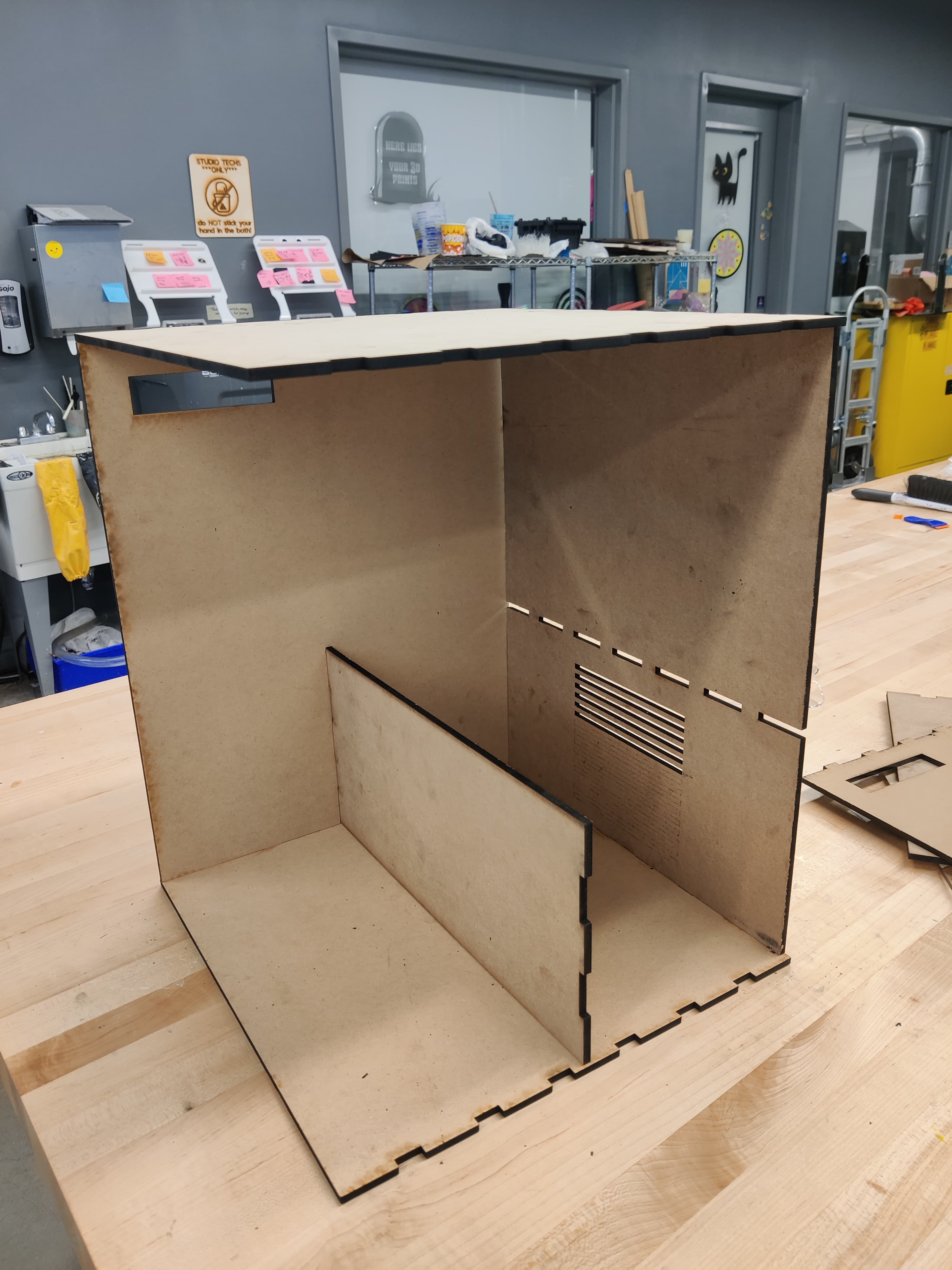
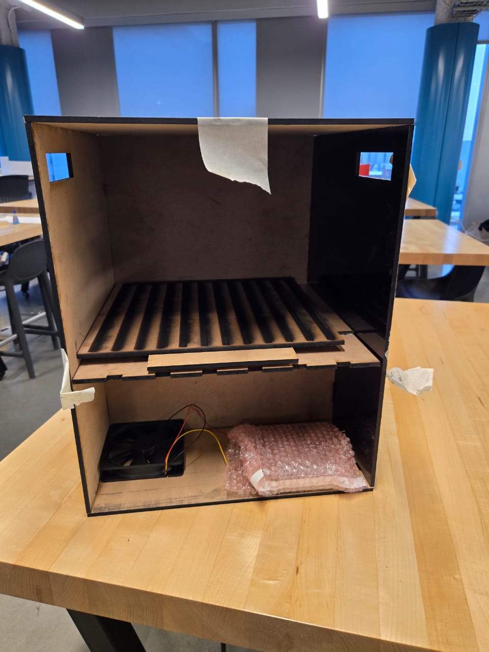
- TWI / I2c code [codes\i2c.c]
- Temperature and Humidity sensor library code.
Next week’s plan
- to have a working temperature and humidity code
- as well as a working Weight sensor code
- All these codes atleast display the outputs on the MOBAEXTERM
- To start with The codes for relay switches, for when the heater will be turned off.
Estimated time team efforts
- Unfortunately it turns out that one person per sensor was not a proper way to allocate the work distribution, venky and komalika both have been working to understand the twi codes together.
- we plan to work on the weight sensor together as well, as soon as we are done with the working of the H&T sensor code.
Sprint review #1
- We had added all our details in the trial sprint review so that we wont need to add much in the first one seperately.
- Much of the review will be a repitition of the trial sprint. All the new details will be HIGHLIGHTED IN BOLD
Current state of project
- Finalized the design of the project.
- Working on CAD design for placement of each component and sensor on the hardware model.
- Finalized the required parts and planning to design the external enclosing based on the dimensions of parts ordered. (Planning to use Birchwood from Tagen hall for making the final enclosing).
- Block Diagram of the Project has been made (and is attached).
- Reviewed the sequential logic of code required for the project.
- Currently Working on a final circuit diagram so that we can test the ordered components.
- Ordered all the parts of our project. Haven’t ordered backups as at this point we did not need any.
- Each Meet’s progress was noted down thoughout the week. (will be shared below)
- Psudo codes have been written
- Box design has been finalized
- Box has been made (We are almost done at the moment of this documentation, will be finished by the end of the day)
Last week’s progress
Week 2 Meeting Reviews
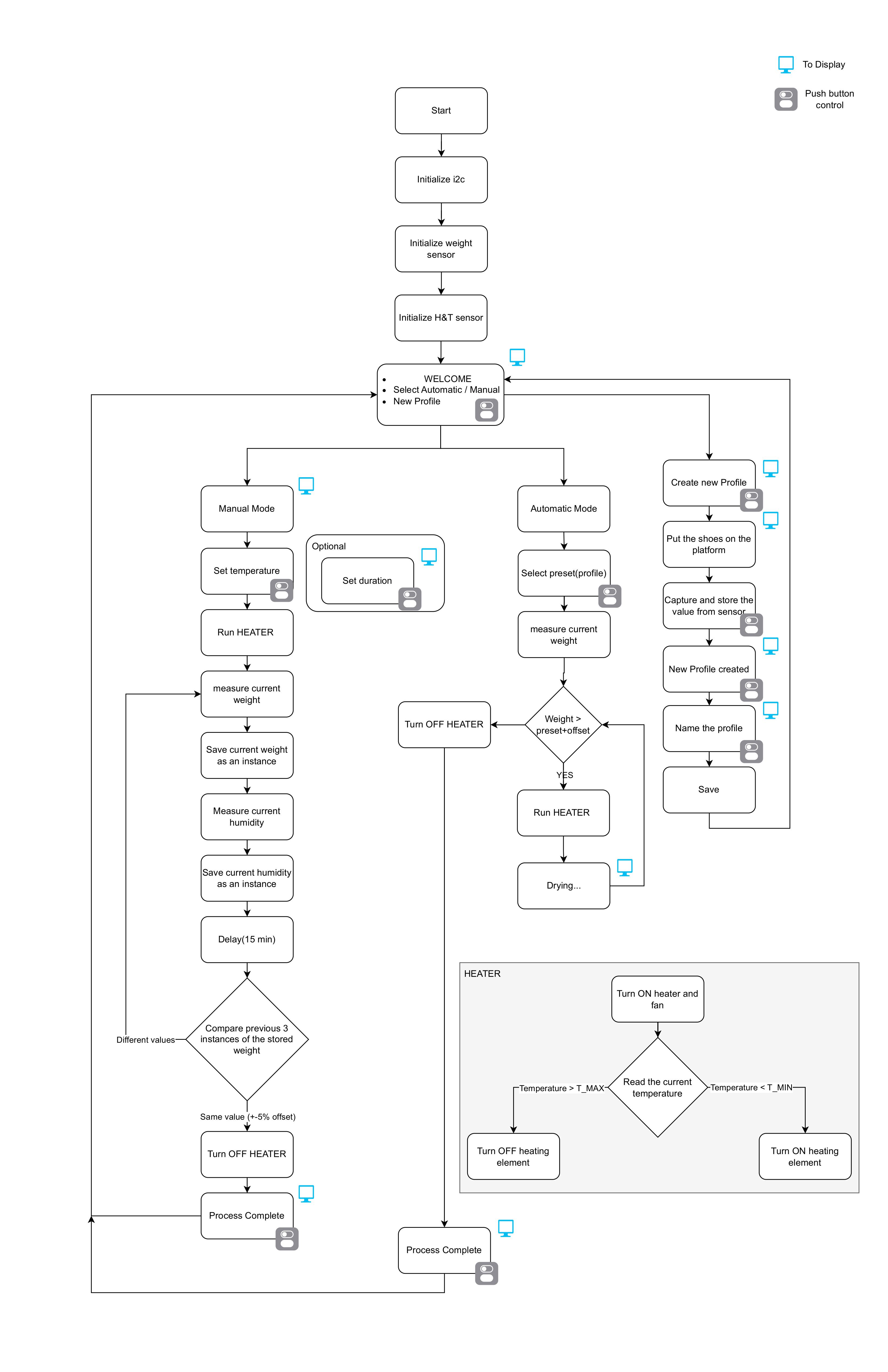
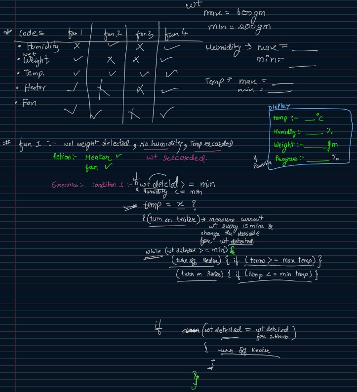
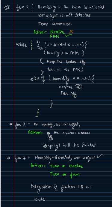
We had worked on implmenting the functional flow chart to review the logical execution of the entire code.
- Design of the project is finalized
- Cirucit Diagram
- BOM and materials have been ordered
- block diagram design started
- Code execution review started
Week 2 work implemenation
- Box has been built from scratch @RPL
- Components Have been recieved (Only the AC- DC relay hasn’t yet arrived)
- CAD design has been Finalized for the BOX
Next week’s plan
- Testing of the components that have been ordered.
- Working Block Diagram to be ready by next monday.
- Working blocks for the code to be started.
- Plan to commit 10- 12 hrs for the coding formats. since coding will take up maximum time.
- Hardware design to be made ready in woodwork from tangen hall.
- Components to be assembled in the hardware.
- The biggest risk for us is the sequencing of different components using baremetal C and to implement the weight measurement mechanism.
- checking O/Ps for each components and getting the outputs correctly.
Estimated time
| Name | Planned Tasks | Allotted time (Hrs) |
|---|---|---|
| Komalika | datasheet reading, Coding logic and pseudocode | 6 |
| Venkatesh | datasheet reading, Coding logic and pseudocode | 6 |
| Aditya | datasheet reading, CAD design | 6 |
Sprint review trial
Current state of project
- Finalized the design of the project.
- Working on CAD design for placement of each component and sensor on the hardware model.
- Finalized the required parts and planning to design the external enclosing based on the dimensions of parts ordered. (Planning to use Birchwood from Tagen hall for making the final enclosing).
- Block Diagram of the Project has been made (and is attached).
- Reviewed the sequential logic of code required for the project.
- Currently Working on a final circuit diagram so that we can test the ordered components.
- Ordered all the parts of our project. Haven’t ordered backups as at this point we did not need any.
- Each Meet’s progress was noted down thoughout the week. (will be shared below)
Flow Chart
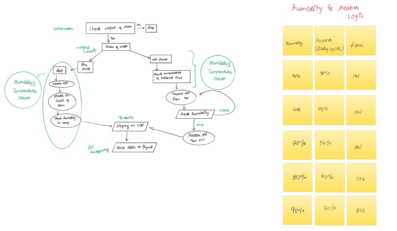
BOM and materials have been ordered
Updated design
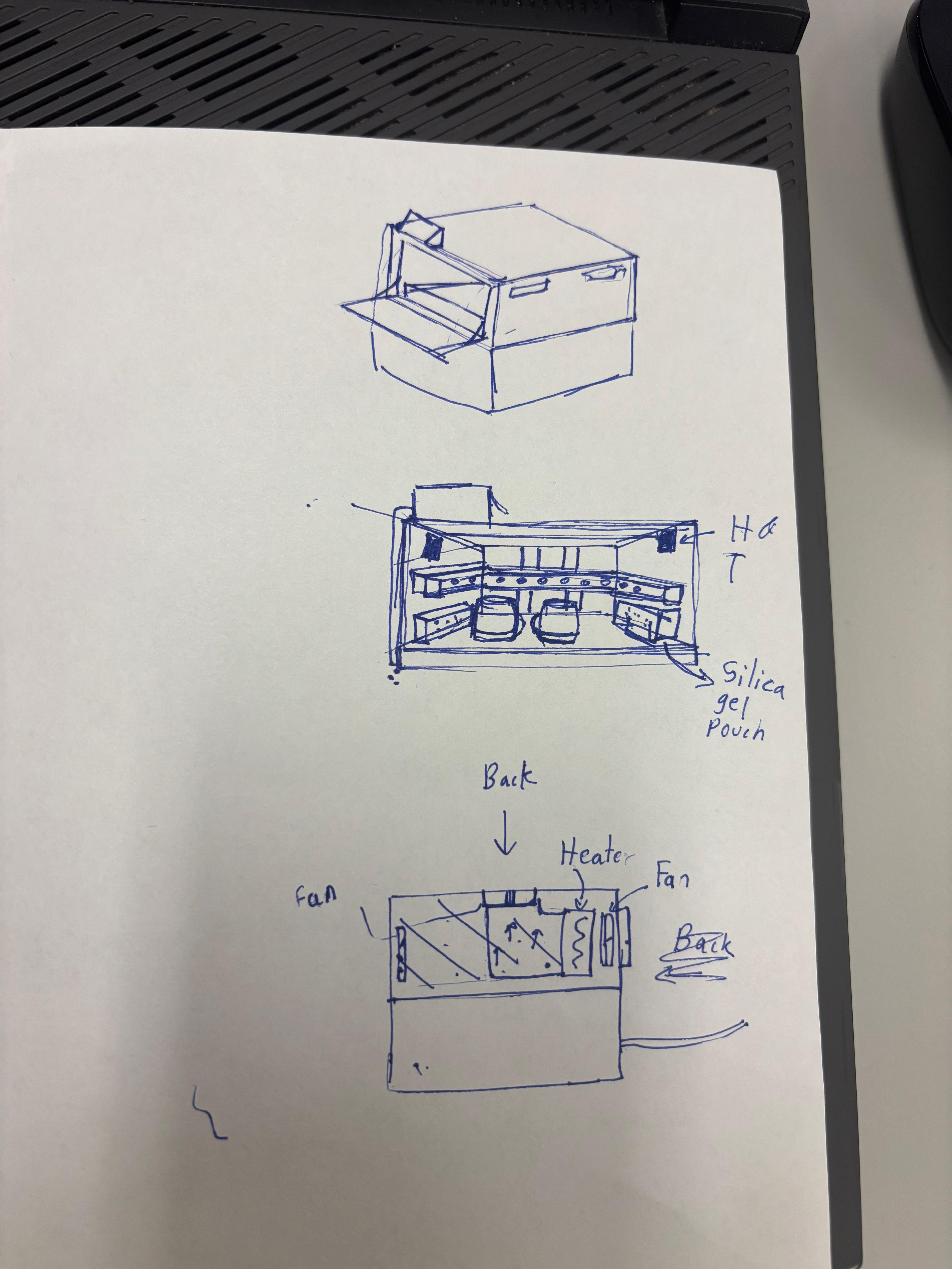
Code execution Flowchart
Last week’s progress
Week 1 Meeting Reviews
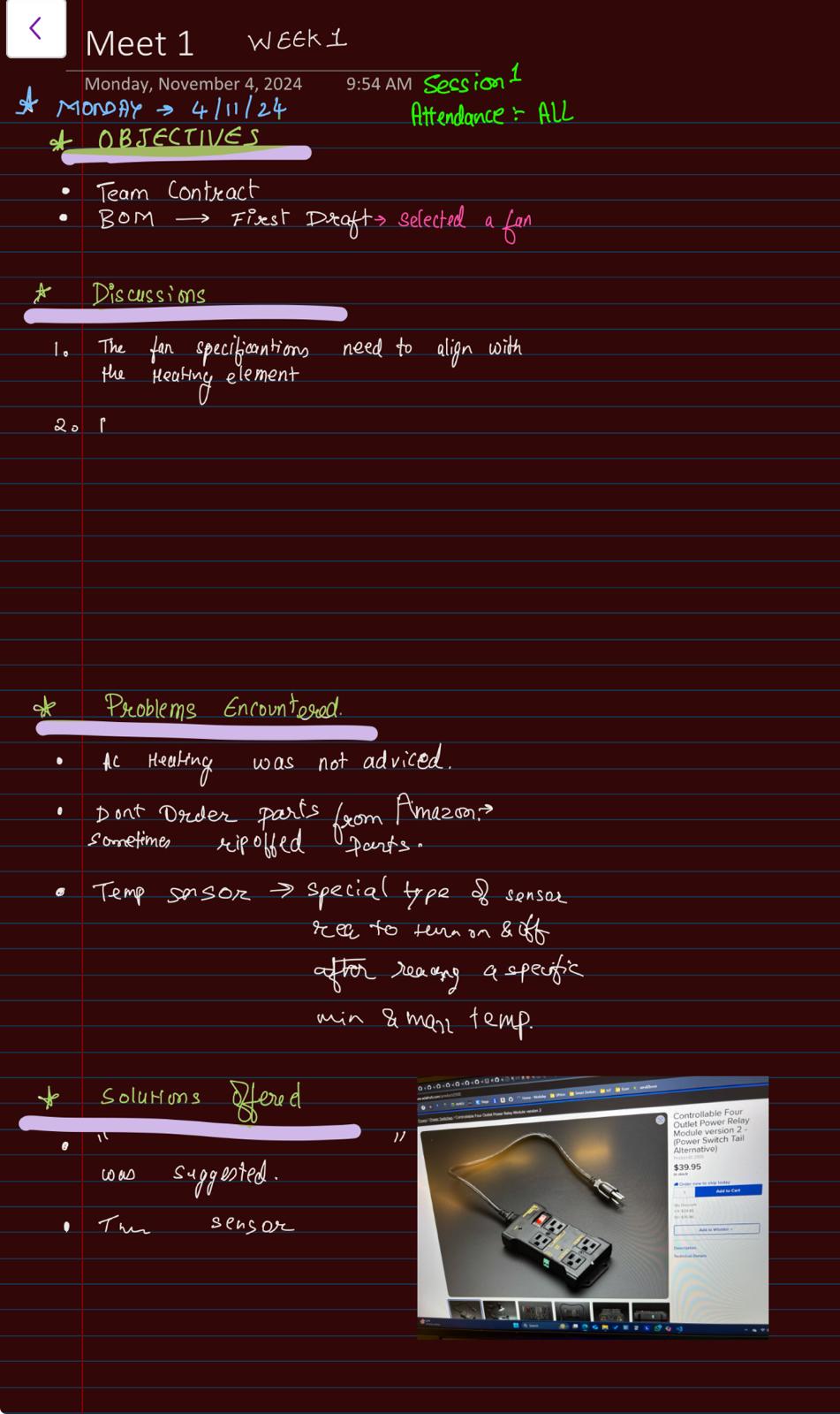
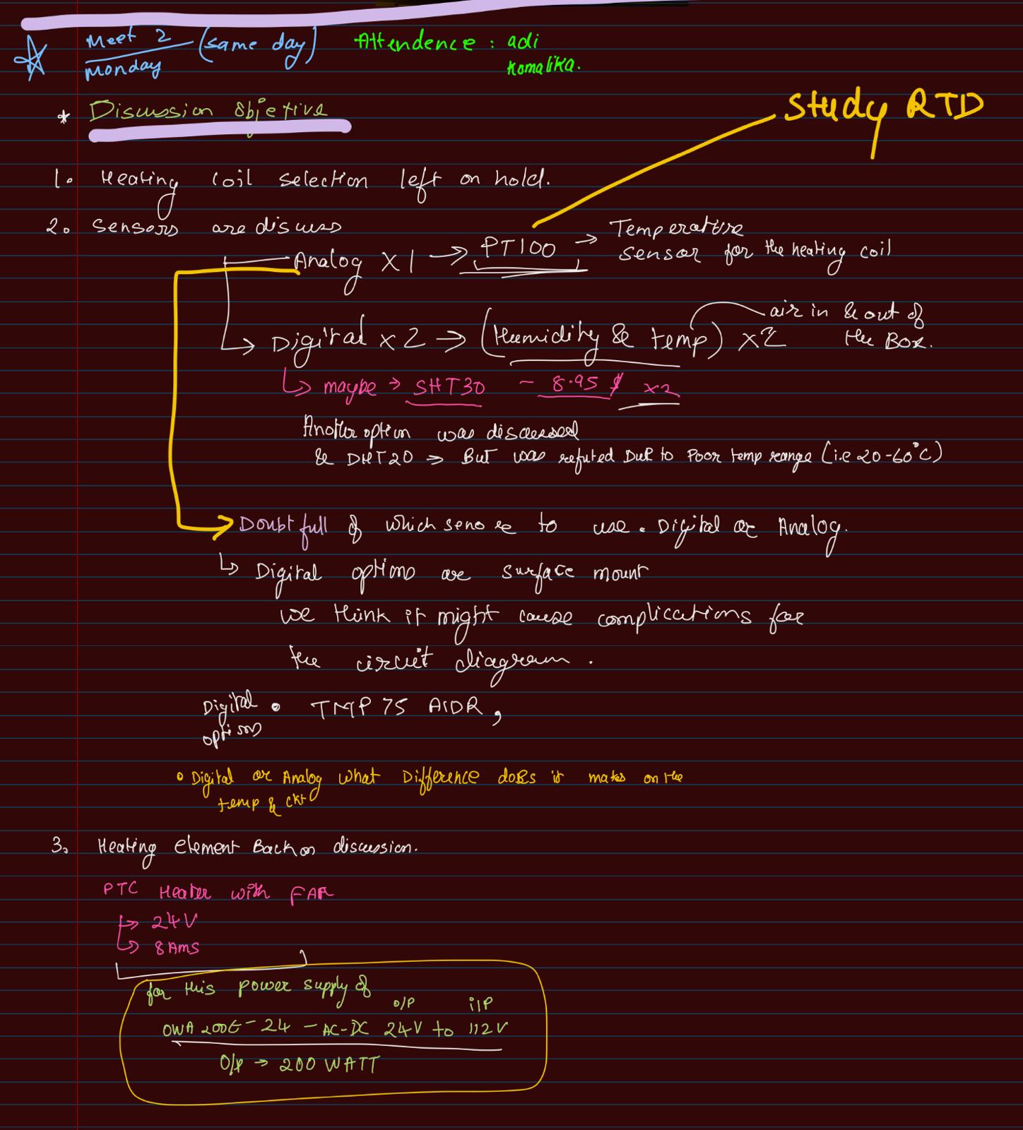
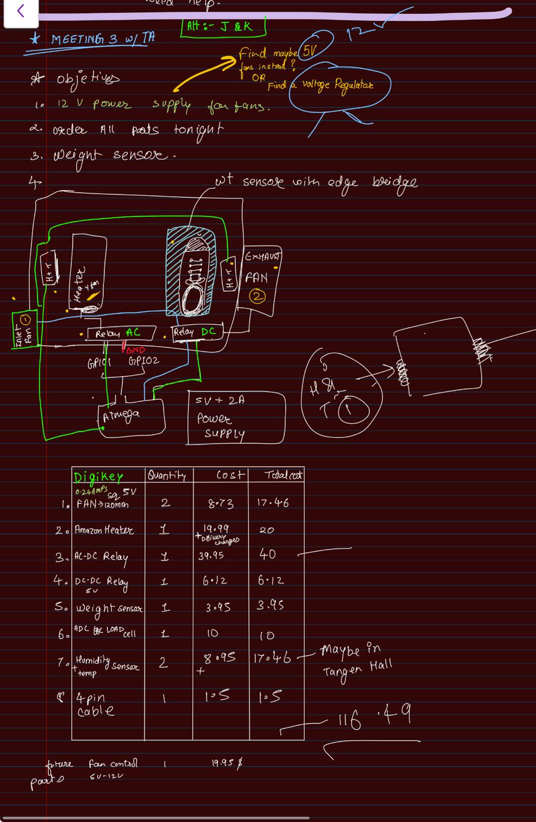
- Design of the project is finalized
- Cirucit Diagram
- BOM and materials have been ordered
- block diagram design started
- Code execution review started
Next week’s plan
- Testing of the components that have been ordered.
- Working Block Diagram to be ready by next monday.
- Working blocks for the code to be started.
- Plan to commit 10- 12 hrs for the coding formats. since coding will take up maximum time.
- Hardware design to be made ready in woodwork from tangen hall.
- Components to be assembled in the hardware.
- The biggest risk for us is the sequencing of different components using baremetal C and to implement the weight measurement mechanism.
- checking O/Ps for each components and getting the outputs correctly.
Estimated time
| Name | Planned Tasks | Allotted time (Hrs) |
|---|---|---|
| Komalika | datasheet reading, Coding logic and pseudocode | 6 |
| Venkatesh | datasheet reading, Coding logic and pseudocode | 6 |
| Aditya | datasheet reading, CAD design | 6 |
Final Project Proposal
1. Abstract
In a few sentences, describe your final project. This abstract will be used as the description in the evaluation survey forms.
SoleDry SoleDry is a sustainable solution designed to dry wet shoes, prevent bad odors, and extend shoe lifespan, especially during the monsoon season. The system uses humidity and temperature control to efficiently dry shoes overnight without causing damage. A display provides real-time updates on weight, temperature, and humidity, allowing users to monitor the drying process effectively. This prototype demonstrates the feasibility of maintaining shoe freshness and durability through automated environmental control.
2. Motivation
What is the problem that you are trying to solve? Why is this project interesting? What is the intended purpose?
Problem: Wet shoes, especially in countries with long rainy seasons, lead to bad odors, bacterial growth, and a shorter shoe lifespan. Traditional drying methods are often inefficient and can damage shoes due to improper temperature control or excessive moisture retention, making it difficult to maintain shoe quality and hygiene.
Interesting Because: SoleDry provides an innovative, automated solution to a common problem by using real-time humidity and temperature control to efficiently dry shoes without compromising their quality. It’s particularly useful in humid climates, offering a sustainable way to extend shoe lifespan and improve hygiene.
Intended Purpose: The goal is to create an efficient, user-friendly system that dries shoes overnight, prevents odor, and maintains the structural integrity of shoes. It ensures shoes remain fresh and usable, making it a convenient and sustainable tool for everyday life, especially during wet seasons.
3. Goals
These are to help guide and direct your progress.
- Maintaining Air Flow: Ensure proper air circulation through vents, exhausts, and fans to promote efficient and uniform drying of shoes.
- Humidity Control: Use sensors and controlled air flow to regulate and maintain optimal humidity levels, preventing excess moisture or drying too fast.
- Temperature Control: Incorporate a reliable heating system to control the temperature inside the box, ensuring shoes dry efficiently without overheating.
- Weight Monitoring: Utilize a weight sensor to track the reduction in shoe weight, enabling precise monitoring of moisture loss during drying.
- LED Display: Show real-time values for humidity, temperature, and weight, along with a calculated percentage indicating how much the shoes have dried based on initial and dry weights.
- Buzzer Notification: Include an alert system (buzzer) to notify the user when the desired dry weight is achieved, signaling that the shoes are fully dry.
4. System Block Diagram

5. Design Sketches

6. Software Requirements Specification (SRS)
6.1 Overview
SoleDry, is a system designed to automate the process of drying wet shoes. The software controls various input devices such as humidity, temperature, and weight sensors, as well as output devices like relays, fans, and heaters. The system processes sensor data, makes decisions based on pre-set thresholds, and displays real-time data to the user on an integrated display and through IoT (Blynk) connectivity for remote monitoring and control.
6.2 Users
- Primary Users: Individuals looking to dry their shoes in a controlled environment, especially in regions with long rainy seasons or humid climates.
- System Administrators: Users responsible for setting up and maintaining the hardware and software, adjusting thresholds and monitoring performance.
- Remote Users: Individuals who want to monitor and control the drying process through the Blynk IoT platform via their mobile devices.
6.3 Definitions, Abbreviations
- ATmega328pb: The microcontroller used to control output devices and read sensor data.
- ESP32: A microcontroller with built-in Wi-Fi for IoT capabilities, used for remote monitoring and control.
- Blynk IoT: A platform for remote device monitoring and control through mobile applications.
- SRS: Software Requirements Specification.
- PWM: Pulse Width Modulation used to control fan speed.
6.4 Functionality
SRS 01 – Humidity and temperature sensors will continuously monitor the environment, sending data to the ATmega328pb every second and send heater temperature every second as well and its getting compared every 30 seconds.
SRS 02 – The weight sensor will measure and update the shoe weight with a precision of 20 grams, and values will be logged every 30 seconds.
SRS 03 – Relay switches will control the heater and fans based on pre-set temperature thresholds at 30°C , observed every 30 second.
SRS 04 – The display will update every second to show the current temperature, humidity, and weight, as well as the percentage of drying progress.
SRS 05 – The user can adjust the mode (Automatic, Manual, and Profile mode) via the buttons, with input processing every 30 seconds. (However for the scope for the final demonstration we are focussing of the automatic mode only.)
7. Hardware Requirements Specification (HRS)
7.1 Overview
System detects the weight of wet shoes placed inside a box and turns on the heating mechanism based on the weight, temperature, and humidity inside the box. The system uses a heating coil for drying, with fans circulating hot, dry air. Sensors continuously monitor the coil’s temperature to prevent overheating. A display shows the weight of the wet shoes and calculates the estimated time to dry the shoes completely, providing real-time feedback.
7.2 Definitions, Abbreviations
- ATmega328pb: A low-power microcontroller used to control relays, heater, and fans based on sensor inputs.
- ESP32: A Wi-Fi-enabled microcontroller responsible for wireless communication and remote control via Blynk IoT.
- LCD: Liquid Crystal Display used to show real-time stats (humidity, temperature, weight) to the user.
- Relay: An electrical switch used to control high-power devices like the heater and fans
7.3 Functionality
- HRS 01 – The project shall be based on the ATmega328pb microcontroller to control relays, heating coil, fans, and process sensor data.
- HRS 02 – A sensor shall be used to detect the weight of the wet shoe placed in the box. The sensor shall measure weight with an accuracy of 20 grams and send data to the microcontroller.
- HRS 03 – A heater shall be used as the drying element. The coil’s temperature shall be continuously monitored by a temperature sensor to avoid overheating. The system shall shut down the coil if the temperature exceeds a preset limit that 30°C.
- HRS 04 – Two 5V fans shall be used to ensure the circulation of hot air inside the box. The fans shall operate in conjunction with the heating coil to provide an even airflow.
- HRS 05 – An LCD display shall be used to show the real-time weight of the shoe and the estimated drying time. The drying time will be calculated based on the weight and environmental conditions (temperature and humidity).
- HRS 06 – A temperature and humidity sensor shall be used to monitor the humidity and temperature inside the box, ensuring optimal drying conditions are maintained.
- HRS 07 – Relays shall control the power supply to the heating coil and fans, turning them on or off based on the shoe weight, temperature, and humidity readings.
- HRS 08 – A 5V power supply block shall power the microcontrollers and input devices, while a 12V power supply shall be used for the relays and output devices (fans), AC supply for the Heater.
8. Components
What major components do you need and why? Try to be as specific as possible. Your Hardware & Software Requirements Specifications should inform your component choices. Add links to components.
ATatemga328pb https://www.digikey.com/en/products/detail/microchip-technology/ATMEGA328PB-XMINI/5338500
Serves as the main controller for the smart shoe dryer, managing core device functions like sensor readings, relay control for the heating element and fan, and display output.
ESP32 https://www.adafruit.com/product/5000
Provides Wi-Fi connectivity and enables remote control and monitoring through the Blynk IoT platform, allowing users to check and manage the dryer remotely.
1.8” LCD Display https://www.adafruit.com/product/358
Used for user interface and interaction. Displays current humidity, temperature and allows for manaual control.
Heater https://www.amazon.com/Amazon-Basics-Portable-Protection-Lightweight/dp/B074MXC3PN?source=ps-sl-shoppingads-lpcontext&ref_=fplfs&smid=ATVPDKIKX0DER&th=1
The main source of heat for the entire system, provides heat and warms up the incoming air.
Fans https://www.digikey.com/en/products/detail/same-sky-formerly-cui-devices/CFM-A225C-015-287-20/14557939
There are 2 fans, one for inlet and other as an exhaust. Both used strategically to control the inside humidity and temperature i.e improve ventilation.
Load sensor https://www.adafruit.com/product/4541
Detects whether the shoes are kept in the rack or not and also measures the weight that is then considered as to how long will it take for the footwear to dry completely.
24-bit ADC for Load Cells / Strain Gauges
https://www.adafruit.com/product/5974
It provides a 24-bit differential ADC, which means it can detect very small changes in resistance, making it perfect for precise measurements
Temperature and humidity sensor
https://www.adafruit.com/product/5989
Detects the inside as well as outside temperature and humidity and helps determine how hot the heater must get and how fast the fans must spin to better dry the footwear quickly.
Joystick and button https://www.adafruit.com/product/444 https://www.adafruit.com/product/1505
Used as means of input devices for the display.
STEMMA QT / Qwiic JST SH 4-Pin Cable
https://www.adafruit.com/product/5385
It is a versatile cable used primarily for connecting sensors and modules in a simple and efficient manner.It supports I2C communication, which is a common protocol for connecting multiple devices using just two wires (SDA for data and SCL for clock)
9. Final Demo
What do you expect to achieve by the final demonstration or after milestone 1?
- By Milestone 1, we expect to:
- Have a finalized component list.
- Place orders for all required parts (sensors, relays, microcontrollers, etc.).
- Begin working on setting up basic components such as switches, clock settings, and initial coding for the microcontroller.
- By the Final Demonstration Day, we expect to:
- Have a fully functional prototype.
- Complete several successful test runs to demonstrate the system’s ability to dry shoes efficiently using humidity, temperature, and weight control.
- Showcase the system’s display, user interface, and Blynk IoT integration for remote monitoring and control.
10. Methodology
What is your approach to the problem? Our approach to designing a smart shoe dryer tackles the problem of wet and odorous shoes by combining efficient drying with hygiene management and user-friendly controls. Here’s the breakdown:
Core Functionality:
- Moisture & Odor Control: We’re incorporating a heating element with a fan to circulate warm air, promoting quick drying while minimizing condensation. An odor and germ filter is included to reduce bacteria and odors, addressing the hygiene aspect effectively.
- Temperature and Humidity Monitoring: Sensors monitor real-time conditions inside the dryer to optimize heating intensity and ventilation based on moisture levels.
Automation & Safety:
- Controlled by ATmega328PB: The ATmega328PB serves as the main controller, processing sensor inputs to dynamically adjust the heater and fan, maintaining safe and effective drying without overheating.
- Relay and Safety Logic: The ATmega controls relays to manage high-power components, ensuring safe and responsive device operation.
User Experience & Remote Control:
- Local Display for Status: A compact OLED or LCD display shows drying status, humidity, and temperature, giving users a clear, at-a-glance understanding of the device’s operation.
- Wi-Fi & Blynk IoT Integration: The ESP32 module connects the device to Wi-Fi and integrates with the Blynk IoT platform, allowing remote monitoring and control. Users can start, stop, or adjust settings via their smartphone, enhancing convenience and accessibility.
Design and Maintenance:
- Modular & Lightweight Design: The dryer will have a modular, lightweight enclosure that is easy to disassemble for cleaning, ensuring that maintenance is minimal and user-friendly.
11. Evaluation
- Drying Time: One of the primary metrics is the time it takes to dry the shoes. The initial target is to dry the shoes within 6 hours. Future improvements will focus on reducing this drying time without increasing energy consumption or causing any damage to the shoes.
- Accuracy of Dryness Detection: The system will use both weight and humidity as measures to determine when the shoes are fully dry. The accuracy of these readings like the weight fluctuation within +/- 50 grams and relative humidity levels, will be key in ensuring the shoes are dried without being overexposed to heat, which can damage them.
12. Proposal Presentation
Add your slides to the Final Project Proposal slide deck in the Google Drive.
https://docs.google.com/presentation/d/1UlWTaDfhGs1sIeoClrVQAtH8inhLJokr/edit?usp=sharing&ouid=103026498329444088626&rtpof=true&sd=true

