
Final Project
Team Number:17
Team Name: RC Car Game
| Team Member Name | Email Address |
|---|---|
| David Aquino | aquinod@seas.upenn.edu |
| Alexander Freeman | alfre@seas.upenn.edu |
| Lucas Krippendorff | lukr@seas.upenn.edu |
| Anil Ghosh | atghosh@seas.upenn.edu |
GitHub Repository URL: https://github.com/upenn-embedded/final-project-s26-t17#
GitHub Pages Website URL: https://upenn-embedded.github.io/final-project-s26-t17/
Final Project Proposal
1. Abstract
Our project is a 2-player game of “tag” with RC cars. Each player is given a controller to control their vehicle, with one player starting as the chaser and one starting as the runner. If the chaser is able to bump/tag the runner, then the roles reverse after a 5 second cool down period. Roles will be indicated by the LCD screen on the top of the car. The game will end after a certain amount of time has elapsed and the current chaser will be crowned the winner.
2. Motivation
The primary motive of the game is for the function of entertainment. A standout feature of this game will be the collision detection and role switching between the two vehicles. On top of this, SPI communication between the MCU and LCD in conjunction with the wireless communication between the controller and cars MCU are other notable features that will require technical exploration and thought. Ultimately, the game itself will not only be fun, but the technical breadth required to realize the project will also provide us with a unique set of engineering problems to solve (and learn from).
3. System Block Diagram
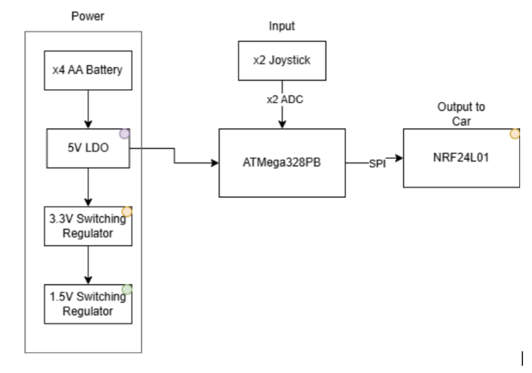
controller diagram:
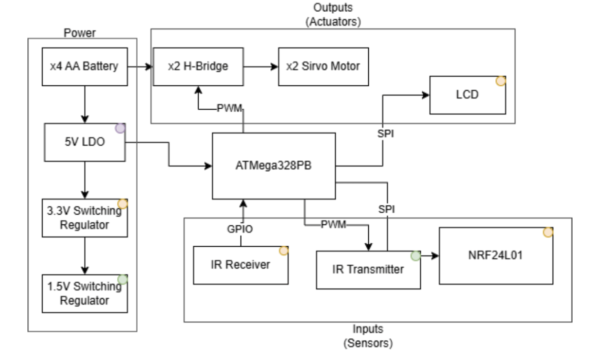
car diagram:
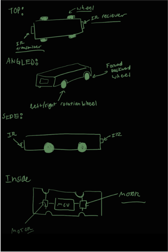
4. Design Sketches
5. Software Requirements Specification (SRS)
5.1 Definitions, Abbreviations
Here, you will define any special terms, acronyms, or abbreviations you plan to use for hardware
5.2 Functionality
| SRS-01 | Remote Drive Response: The vehicle shall respond to valid remote control drive commands within 100 ms of transmission, including forward, reverse, left, right, and stop commands. Validation: Timestamp controller transmission and observed motor actuation using serial logs and/or video frame analysis. |
|---|---|
| SRS-02 | Continuous Motor and Steering Control: The firmware shall update motor speed and steering control signals at a rate of at least 20 Hz during active vehicle operation. Validation: Measure PWM/control signal update timing with an oscilloscope or logic analyzer while the car is being driven. |
| SRS-03 | IR Tag Detection: The system shall detect a valid IR tag event when the rear-mounted IR receiver detects a modulated IR signal from the opposing vehicle for a minimum number of consecutive samples. Validation: Perform controlled alignment tests and verify that valid IR transmissions consistently trigger detection while ambient light does not. |
| SRS-04 | Tag Validation and Cooldown Logic: The system shall confirm a tag event only after satisfying a defined detection condition and shall enforce a cooldown period of at least 1 second during which additional tags are ignored. Validation: Simulate repeated IR exposure and verify that only valid, non-overlapping tag events are registered. |
| SRS-05 | Role Switching via Wireless Communication: Upon detection of a valid tag event, the system shall transmit a role-switch message and update the chaser/runner roles on both vehicles within 200 ms. Validation: Trigger tag events and verify synchronized role updates on both cars using debug logs and observed IR transmitter activation. |
| SRS-06 | Directional Tagging Behavior: The system shall only register a tag when the chaser’s front-mounted IR transmitter aligns with the runner’s rear-mounted receiver. Validation: Test various orientations between vehicles and confirm that tags are only registered when the chaser is positioned behind the runner. |
| SRS-07 | Game State Feedback: The system shall provide real-time visual feedback indicating the current role (chaser or runner) and tag events. Validation: Trigger role changes and tag events and verify correct display outputs. |
6. Hardware Requirements Specification (HRS)
6.1 Definitions, Abbreviations
Here, you will define any special terms, acronyms, or abbreviations you plan to use for hardware
6.2 Functionality
| HRS-01 | Drive Motor Actuation: The vehicle shall include a motor drive subsystem capable of driving the car forward and reverse across a flat indoor surface under onboard power. Validation: Test the car on a flat surface and verify successful forward and reverse motion over a fixed distance. |
|---|---|
| HRS-02 | Steering Mechanism: The vehicle shall include a steering mechanism that enables controlled left and right turning during remote operation. Validation: Command left and right turns and verify directional change through observed turning maneuvers or measured turning radius. |
| HRS-03 | IR Transmission Subsystem: Each vehicle shall include a forward-facing IR transmitter driven by a PWM signal (~38 kHz) to emit a detectable signal for tagging. Validation: Verify IR emission using an IR receiver module or camera and confirm proper modulation. |
| HRS-04 | IR Reception Subsystem: Each vehicle shall include a rear-mounted IR receiver module capable of detecting modulated IR signals from the opposing vehicle. Validation: Confirm reliable detection of transmitted IR signals at distances up to the specified gameplay range of ~6 -10 inches. |
| HRS-05 | Wireless Communication Interface: Each vehicle shall include a wireless transceiver (nRF24L01) interfaced via SPI to enable communication with its controller and the opposing vehicle. Validation: Verify bidirectional communication by transmitting and receiving control and game-state packets. |
| HRS-06 | Status Feedback Hardware: Each vehicle shall include an LCD Display to communicate role status and tag events to the user. Validation: Trigger system states and verify correct activation of LCD. |
| HRS-07 | Regulated Power Distribution: Each vehicle shall include a power subsystem that provides regulated voltage levels for logic components (MCU, sensors, RF module) and motor actuation components. Validation: Measure voltage levels under idle and active conditions and verify stable operation. |
7. Bill of Materials (BOM)
Remote: STM nucleo NRF24L01 transceiver module Thumbstick potentiometer (x2) Start/reset button 7-segment or small numeric display (timer readout) AA battery pack + holder
Car: STM nucleo NRF24L01 transceiver module Mecanum wheel chassis DC gear motor Steering Servo Motor H-bridge motor driver (x2) LEDs (x2) AA battery pack + holder
8. Final Demo Goals
On demo day, the project will be demonstrated using two small RC cars operating on the floor in an open indoor space such as a classroom or lab area. One car will act as the chaser and the other as the runner. Each vehicle will be controlled by a player using its control interface. During the demonstration, the runner will attempt to avoid the chaser while moving around the designated area, while the chaser will attempt to approach the runner and trigger a tag event by entering a predefined proximity range. When the tag condition is met, the runner vehicle will automatically enter a disabled state where its motors stop and a visual or audible indicator (such as an LED or buzzer) signals the tag event. The demonstration will require approximately 2–3 meters of open floor space and will last about one to two minutes, allowing time to show vehicle movement, proximity detection, and the tag response. The cars will be powered by onboard batteries and will include a reset mechanism so the demonstration can be quickly repeated if needed. This setup highlights the integration of sensing, motor control, and embedded game logic within the system.
9. Sprint Planning
| Milestone | Functionality Achieved | Distribution of Work |
|---|---|---|
| Sprint #1 | Basic joystick reading and detailed schematics | Schematics, software, testing, prototyping |
| Sprint #2 | Motor control and SPI | Software, component testing |
| MVP Demo | One semi-driving car with functional controller | Power management, software, testing |
| Final Demo | Two functional driving cars and controller pairs, IR sensing, LCD display | Power management, weight/wire reduction, software |
This is the end of the Project Proposal section. The remaining sections will be filled out based on the milestone schedule.
Sprint Review #1
Last week’s progress
This week we decided to switch boards to STM32. We were able to read 2-joysticks inputs using the ADC’s on the board. This required us to write a simple ADC driver. We also wrote an untested SPI driver to general SPI communication. Additionally we designed a more detailed schematic. (please see Code folder and Images folder)
Current state of project
Currently we are reading the joystick values correctly. Additionally, we have an SPI driver. We also have the parts ordered.
Next week’s plan
By next week, we wish to have all modular moving parts working seperatly. This means ADC driver, SPI communication for LCD AND NRF module, IR sensing, and motors being driven via PWM. These are all the “moving” parts of the project.
Sprint Review #2
Last week’s progress
This week, the primay points of progress where the completion of many of the sub-processess working individually. Namely, we have a 2-joysticks that can independently control two motors (wireless communication is still WIP). Additionally, we have a working SPI driver and libraries for LCD screen display, and IMU read. Please refer to the Code/Libraries(WIP) folder to see all of the driver and library code. Also see below for some images and demos.
Current state of project
Currently Reading various IMU input via SPI driver + Custom IMU Library Code: Click here
Video of Motors being independently and simutaneously controlled via joystick while LCD screen displays simple image: Click here
Controller Hardware Diagram:
Next week’s plan
For next week, we must complete wireless communication and also have a fully working car that can move and respoind to joystick input.
MVP Demo
Car Diagram:
Controller Diagram:
Firmware Breakdown:
For the MVP demo, the firmware was organized around four main responsibilities: joystick input, wireless communication, motor control, and basic game-state feedback. The controller firmware reads two joystick axes through the STM32 ADC, converts each analog value into a signed motor command from -100 to 100, and sends those commands wirelessly to the car using the nRF24L01 module. A small deadzone is applied around the joystick center position so that minor ADC noise does not cause unintended motor movement.
On the car side, the firmware listens for incoming nRF24 packets from its paired controller. Each packet contains two motor commands, one for each drive motor. When a valid packet is received, the car updates the H-bridge direction pins and PWM duty cycles for both motors. The motor driver supports forward, reverse, and stop states, with PWM generated using TIM4 to control speed.
The MVP firmware also includes early integration of the game logic. The runner car monitors its IR receiver for recent activity, and if an IR tag is detected, it enters a game-over state and stops both motors. After this event, the runner car sends a status packet back over the radio link so that the controllers can update their displays. The controller LCD uses simple color feedback to show communication status, player role, and game-over state.
At the MVP stage, the firmware demonstrated the core control loop needed for gameplay: joystick input was successfully converted into wireless motor commands, the car responded to those commands through PWM motor control, and the first version of tag/game-over behavior was integrated. Some final-game features, such as full two-car role switching, cooldown timing, and polished display output, were left for the final demo implementation.
Progress on Requirements
We met our first software requirement SRS-01, as we had continuous response to controller comands by the car without visible delay. SRS-02 was likely satisfied as well but we do not yet have validation of that.
With hardware, we made more porgress. HRS-01, HRS-02, and HRS-07 were all fulfilled. We had drive capability confirmed by observation (the car moved with commands). Our steering also worked in our static test and in our trials of actually driving the car (turning manuevers successfully performed. For HRS-07, we switched from a 6V system to a 9V system which increased the mobility of the car enough to move slowly despite the motors struggling with weight. Our LDO dropped the 9V to 5V which then externally powered out STM32 and H-bridge. The H-bridge then dorpped some votlage and powered the steering and drive motors. While LDOs are not efficient at such a drop, they were more compact and easily usable than our 6V battery packs. 6V was also not very good at getting motors moving as we realized the LDO reduced its input non-trivially.
Next Steps
For the next stretch, we will be focusing on the IR tag system and game logic in addition to some more hardware and power streamlining. The task of greatest importance is to build a second car, which seems risky but can be made alot safer by optimzing our first car design before trying to make a second one. By addressing the weight issues and reducing hardware before attempting another build, we can really save time on the debugging. In particular, cutting down wires and moving from breadboar dot perf board could make movement alot easier. However, an ultimately likely solution would be to replace the motors with higher torque versions such as those we initially ordered.
Final Report
Don’t forget to make the GitHub pages public website! If you’ve never made a GitHub pages website before, you can follow this webpage (though, substitute your final project repository for the GitHub username one in the quickstart guide): https://docs.github.com/en/pages/quickstart
1. Video
Click here to watch the report video.
The video shows the cars and remotes operating separately, demonstrating the wireless control link. Each controller is paired with a unique car (each car has its own address). At one point, the second car is placed on the floor but does not move; when the camera pans to its controller, the LCD is red, indicating no connection. Once the car starts moving, the LCD turns green to indicate the connection is live (showcasing bidirectional MCU wireless communication).
2. Images
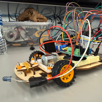
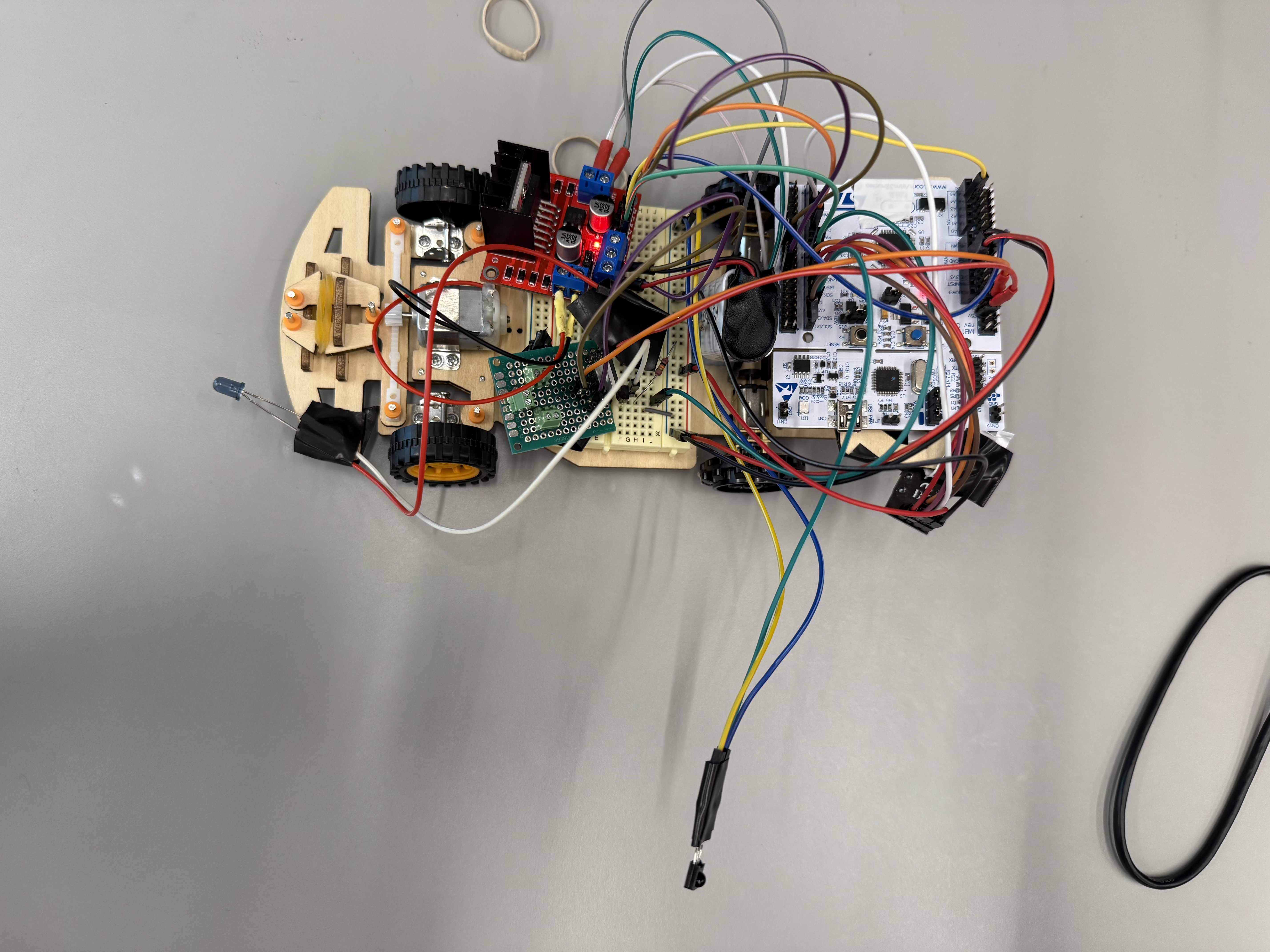
Car (top view) — STM32 Nucleo, NRF24L01 transceiver, LCD, and IR components visible.
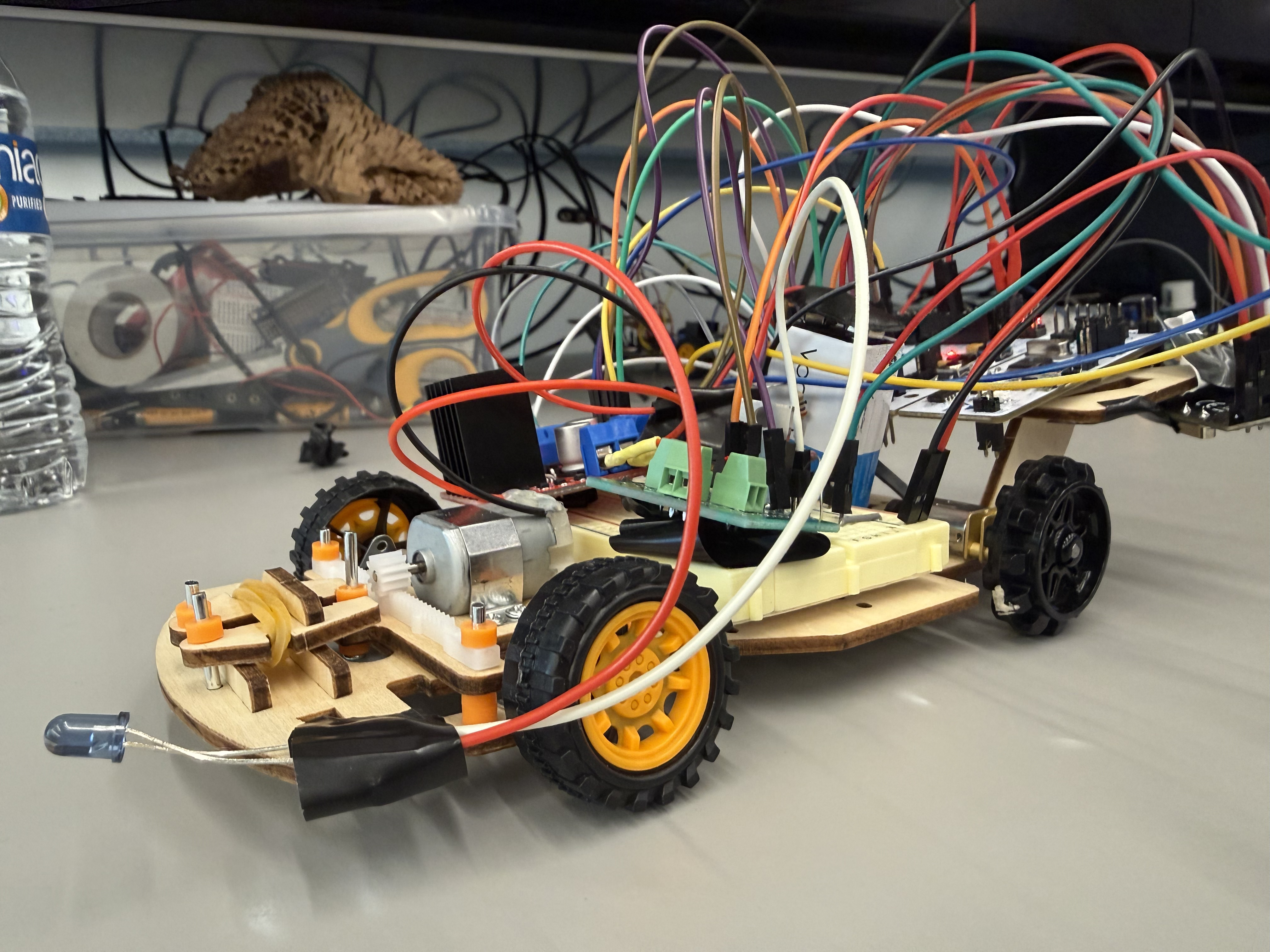
Car (side view) — chassis, motor placement, and rear IR receiver.
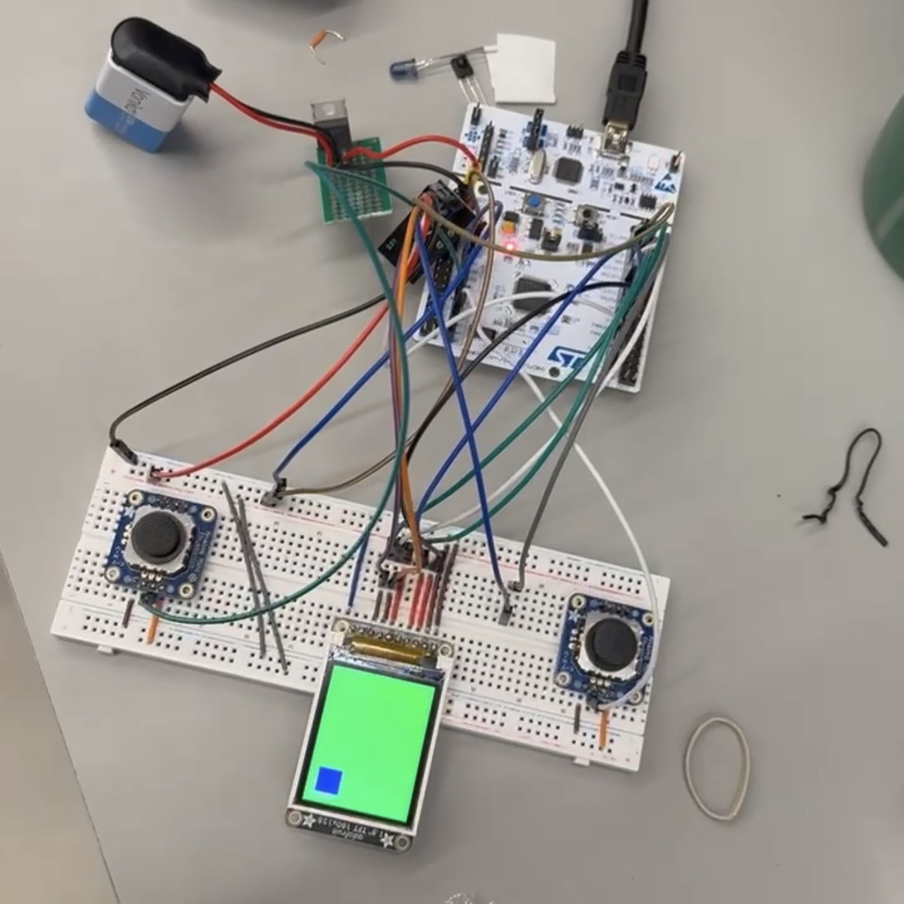
Controller (top view) — dual joysticks, STM32, and NRF24L01.
3. Results
Most software and hardware requirements were met or exceeded; the primary shortfall was the IR-based tag mechanic, which never reached a reliably gameable state due to ambient IR noise.
3.1 Software Requirements Specification (SRS) Results
| ID | Description | Validation Outcome |
|---|---|---|
| SRS-01 | Remote Drive Response: The vehicle shall respond to valid remote control drive commands within 100 ms of transmission, including forward, reverse, left, right, and stop commands. Validation: Timestamp controller transmission and observed motor actuation using serial logs and/or video frame analysis. | Achieved. Joystick->wheel response visible within 1-2 frames at 30 fps (~33-67 ms) in the demo video. Path: ADC -> NRF24 -> motor_set_command() -> TIM4 PWM. FOR VALIDATION PLEASE SEE DEMO VIDEO |
| SRS-02 | Continuous Motor and Steering Control: The firmware shall update motor speed and steering control signals at a rate of at least 20 Hz during active vehicle operation. Validation: Measure PWM/control signal update timing with an oscilloscope or logic analyzer while the car is being driven. | Achieved. TIM4 PWM runs at 1 kHz (PSC=15, ARR=999); the joystick->motor loop updates duty cycle continuously, well above 20 Hz. |
| SRS-03 | IR Tag Detection: The system shall detect a valid IR tag event when the rear-mounted IR receiver detects a modulated IR signal from the opposing vehicle for a minimum number of consecutive samples. Validation: Perform controlled alignment tests and verify that valid IR transmissions consistently trigger detection while ambient light does not. | Partially met. IR proximity detection works at close range but is unreliable due to ambient IR noise; never reached a gameable state. |
| SRS-04 | Tag Validation and Cooldown Logic: The system shall confirm a tag event only after satisfying a defined detection condition and shall enforce a cooldown period of at least 1 second during which additional tags are ignored. Validation: Simulate repeated IR exposure and verify that only valid, non-overlapping tag events are registered. | Not validated. Cooldown logic exists in firmware but SRS-03 never produced reliable tag events to validate against. |
| SRS-05 | Role Switching via Wireless Communication: Upon detection of a valid tag event, the system shall transmit a role-switch message and update the chaser/runner roles on both vehicles within 200 ms. Validation: Trigger tag events and verify synchronized role updates on both cars using debug logs and observed IR transmitter activation. | Partially met. Role-switch firmware and NRF24 packet format implemented; never end-to-end validated due to unreliable SRS-03 trigger. |
| SRS-06 | Directional Tagging Behavior: The system shall only register a tag when the chaser’s front-mounted IR transmitter aligns with the runner’s rear-mounted receiver. Validation: Test various orientations between vehicles and confirm that tags are only registered when the chaser is positioned behind the runner. | Not met. Orientation/alignment behavior was not tested due to SRS-03 unreliability. |
| SRS-07 | Game State Feedback: The system shall provide real-time visual feedback indicating the current role (chaser or runner) and tag events. Validation: Trigger role changes and tag events and verify correct display outputs. | Achieved. LCD updates role indicator on each state transition; visible in the demo video. Driven over SPI using the custom ST7735 driver. |
| FOR VALIDATION PLEASE SEE CONTROLLER TOP VIEW IMAGE |
3.2 Hardware Requirements Specification (HRS) Results
| ID | Description | Validation Outcome |
|---|---|---|
| HRS-01 | Drive Motor Actuation: The vehicle shall include a motor drive subsystem capable of driving the car forward and reverse across a flat indoor surface under onboard power. Validation: Test the car on a flat surface and verify successful forward and reverse motion over a fixed distance. | Achieved. Two rear DC motors via H-bridge drove the car across the full long axis of AGH Detkin Lab, far beyond the few-meter footprint originally targeted. FOR VALIDATION PLEASE SEE DEMO VIDEO |
| HRS-02 | Steering Mechanism: The vehicle shall include a steering mechanism that enables controlled left and right turning during remote operation. Validation: Command left and right turns and verify directional change through observed turning maneuvers or measured turning radius. | Achieved. Front-wheel DC motor on a second H-bridge (TIM4 CH2) gives left/right steering with spring-return centering, replacing the originally-spec’d servo. FOR VALIDATION PLEASE SEE DEMO VIDEO |
| HRS-03 | IR Transmission Subsystem: Each vehicle shall include a forward-facing IR transmitter driven by a PWM signal (~38 kHz) to emit a detectable signal for tagging. Validation: Verify IR emission using an IR receiver module or camera and confirm proper modulation. | Achieved. Forward-facing IR LED driven at ~38 kHz from a hardware timer; emission confirmed via phone camera (visible as a bright spot when modulated). |
| HRS-04 | IR Reception Subsystem: Each vehicle shall include a rear-mounted IR receiver module capable of detecting modulated IR signals from the opposing vehicle. Validation: Confirm reliable detection of transmitted IR signals at distances up to the specified gameplay range of ~6 -10 inches. | Partially met. Reliable detection at ~4 in under low ambient IR (evening, uncrowded lab); unreliable in daylight or busy lab as ambient IR overwhelms the receiver. |
| HRS-05 | Wireless Communication Interface: Each vehicle shall include a wireless transceiver (nRF24L01) interfaced via SPI to enable communication with its controller and the opposing vehicle. Validation: Verify bidirectional communication by transmitting and receiving control and game-state packets. | Achieved (exceeded). NRF24L01 over our custom SPI driver; reliable bidirectional control across the full long axis of AGH Detkin Lab. |
| HRS-06 | Status Feedback Hardware: Each vehicle shall include an LCD Display to communicate role status and tag events to the user. Validation: Trigger system states and verify correct activation of LCD. | Achieved. 1.8” ST7735 LCD over SPI shows the current role indicator and refreshes immediately on state transitions. |
| HRS-07 | Regulated Power Distribution: Each vehicle shall include a power subsystem that provides regulated voltage levels for logic components (MCU, sensors, RF module) and motor actuation components. Validation: Measure voltage levels under idle and active conditions and verify stable operation. | Achieved. 9V battery -> H-bridge motor inputs; 5V LDO supplies the STM32, NRF24L01, and LCD. Stable across idle and active operation. |
4. Conclusion
The project successfully integrated multiple subsystems on bare metal, including custom drivers for SPI, ADC, LCD, motor control, joystick input, and IMU. The wireless link operated reliably across the full long axis of Detkin Lab, well beyond the originally targeted range, and the cars drove and steered consistently throughout the demo.
The primary shortfall was the IR detection subsystem. The receiver’s sensitivity to ambient IR (sunlight and lab lighting) made detection unreliable outside controlled conditions, which prevented the IR-based tag mechanic from reaching a gameable state.
A revision would address the IR subsystem first, likely with an optical bandpass filter, physical shielding around the receiver, and a coded or correlated IR protocol with stronger noise rejection. From there, finishing the tag-and-cooldown game logic on top of a more robust detection layer would complete the originally-scoped gameplay.