final-project-smart-robot
Final-project: Group 14 Smart Robot
* Team Name: Smart Robot
* Team Members: Zhongkun Xue and Toma Yasuda
* Github Repository URL: https://github.com/upenn-embedded/final-project-smart-robot.git
* Github Pages Website URL: https://upenn-embedded.github.io/final-project-smart-robot/
* Description of hardware: EMG Sensor, 328PB, LCD, Serveo, Battery, Voltage Regulator
Final Project Report
Motivation
1. To help people with disabilities or injuries gain the ability to perform everyday tasks that require hand movements.

2.To show the human-machine interaction like the Spider-Man

Video demonstration
GIF demonstration
Gripper part
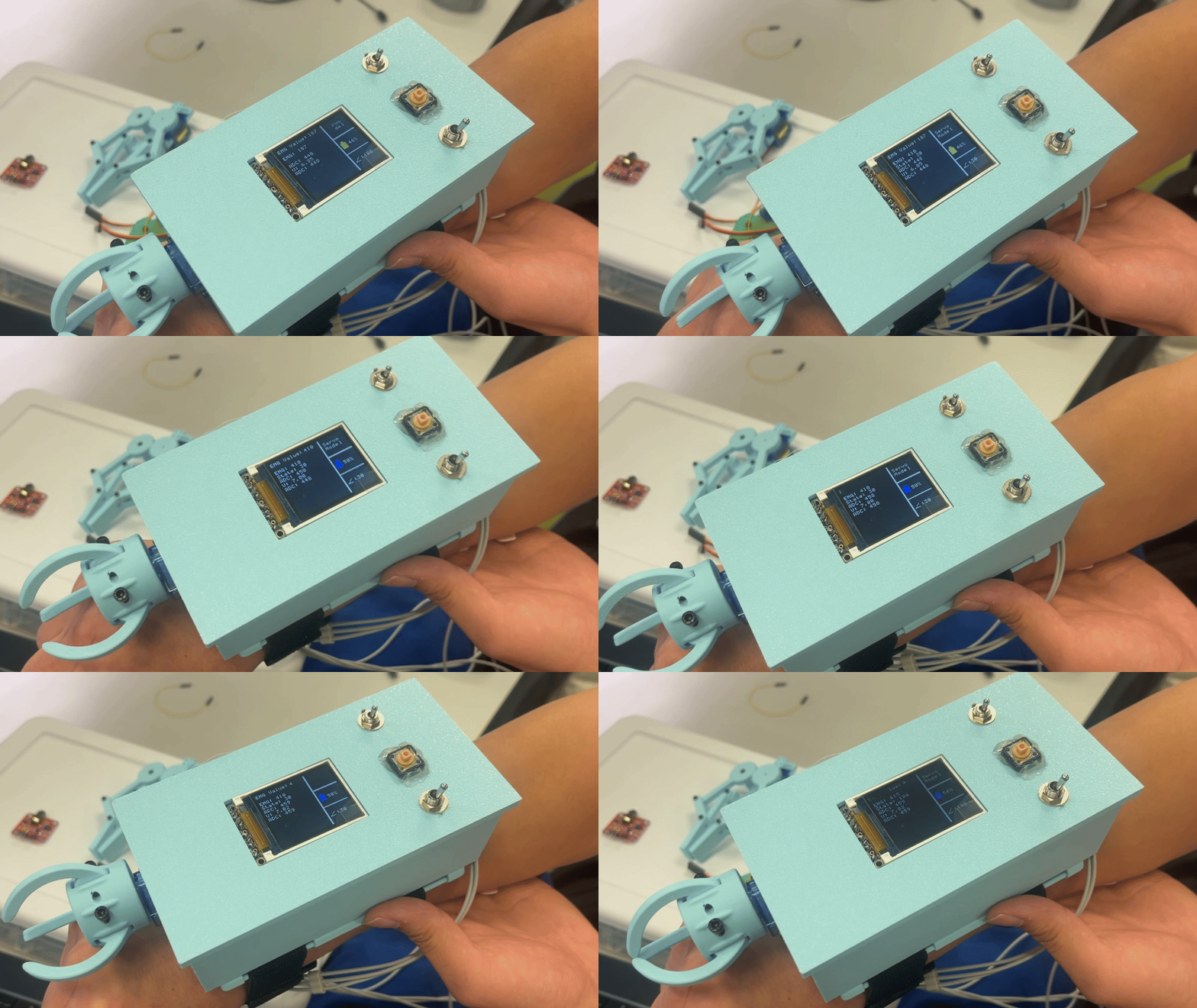
Spider shooter
Images demonstration
firmware_diagram
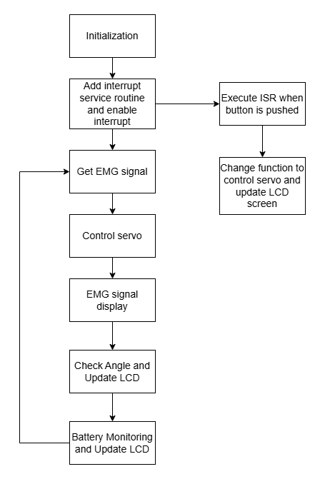
Circuit
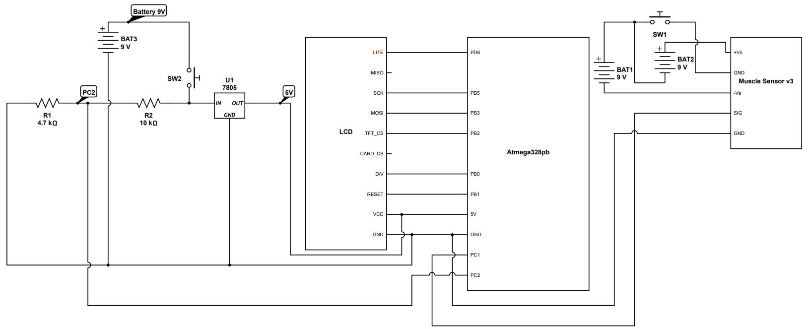
Project

SRS Validation
| Detail | Achievement | |
|---|---|---|
| SRS 1 | The software shall detect EMG signals between 0 and 1024 by ADC, filter noise under, and classify signal strength | Yes |
| SRS 2 | Decision-making algorithms shall open or close the claw within 0.5 seconds of detecting an EMG signal based on EMG signal thresholds, which is 200 | Yes |
| SRS 3 | The system shall include fail-safe controls to prevent accidental or unsafe activation of the claw | No |
| SRS 4 | The system shall include the battery health calculation by ADC to show the percentage of the current battery | Yes |
| SRS 5 | The software will output the PWM to control the servo degree | Yes |
| SRS 6 | The software shall include the ISR to handle the interrupt by the button, ensuring a response time of less than 1 seconds | Yes |
| SRS 7 | The software shall provide a user interface to display the real-time data, including EMG signal, battery health, and claw angle updating every 500 millisecond | Yes |
| SRS 8 | The software shall communicate with the LCD display using SPI protocol to send data | Yes |
SRS 1: The software detects EMG signals between 0 and 1024 by ADC, filters noise under, and classifies signal strength. This requirement was tested by displaying the data corrected by the EMG signals on the serial terminal. The values corrected were between 0 and 1024 by ADC. The data is showed in the video and the final_version.c file.
SRS 02: We measured the time between detecting an EMG signal and claw being opened and closed by displaying the time on the serial monitor. We tested 10 times and the maximum time is less than 0.5 seconds.
| time(s) | |
|---|---|
| 1 | 0.22 |
| 2 | 0.35 |
| 3 | 0.32 |
| 4 | 0.19 |
| 5 | 0.44 |
| 6 | 0.34 |
| 7 | 0.24 |
| 8 | 0.47 |
| 9 | 0.32 |
| 10 | 0.33 |
SRS 03: Not achieved because we did not include fail-safe controls to prevent accidental or unsafe activation of the claw. However, there is a button that can be used to stop the control of servo manually.
SRS 04: Achieved and the system includes battery health calculation by ADC to show the percentage of the current battery on the LCD screen. We tested this requirement by showing battery percentage on the screen and compared it with the measured value by the multimeter. The image of the LCD screen is shown in the video and the images part.
SRS 05: Achieved and the software outputs the PWM to control the servo degree. The servo can move the claw based on the input of the EMG signal. The code of final_version.c is showing the work and the video shows that the servo is controlled by the PWM.
SRS 06: We measured the response time to handle the interrupt by the button by printing on the serial. We tested 10 times and data is shown below.
| time(s) | |
|---|---|
| 1 | 0.34 |
| 2 | 0.54 |
| 3 | 0.43 |
| 4 | 0.41 |
| 5 | 0.44 |
| 6 | 0.56 |
| 7 | 0.89 |
| 8 | 0.54 |
| 9 | 0.50 |
| 10 | 0.67 |
SRS 07: The time to update the LCD screen was measured and displayed on the serial monitor. We can check it from the video.
SRS 08: Achieved and the LCD screen displays the data including EMG signal, battery health, and claw angle. The image of the LCD screen displaying the data from the images part.
HRS Validation
| Detail | Achievement | |
|---|---|---|
| HRS 1 | Project shall be based on ATmega328PB microcontroller operating at 16MHz | Yes |
| HRS 2 | EMG sensors (Myoware Muscle Sensor or equivalent) shall be used for muscle activity detection. The sensor shall detect muscle electrical activity in the range of 0-5V | Yes |
| HRS 3 | A 1.8” Color TFT LCD (ST7735R controller) shall be used for user interface | Yes |
| HRS 4 | System shall include a servo motor with minimum 180-degree rotation capability for mechanical actuation controlled by PWM | Yes |
| HRS 5 | Power supply shall be provided by a portable battery pack capable of supplying 5V DC or convert to 5V | Yes |
HRS 01: Achieved. ATmega328PB microcontroller operating at 16MHz is used for this project. The proof is in the code which is final_version.c file.
HRS 02: Myoware Muscle Sensor is used, the connection is good. The circuit image shows the voltage range and the funciton of the sensor in video shows it works well.
HRS 03: Achieved. A 1.8” Color TFT LCD (ST7735R controller) to display data for users. The proof is in our video.
HRS 04: Achieved. A servo motor with 180-degree rotation capability for mechanical actuation controlled by PWM is used for our project. Here is the link for the datasheet of the servo.
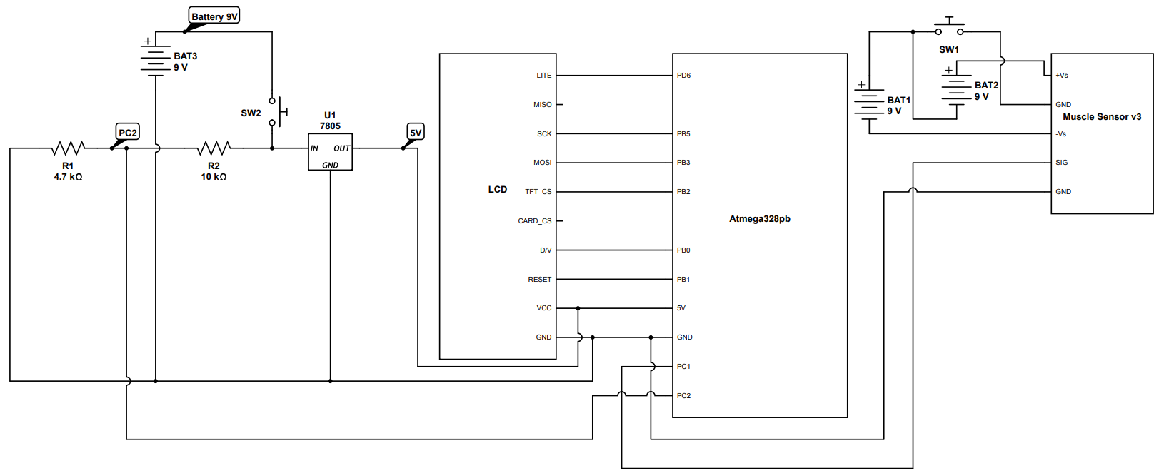
HRS 05: A 9V battery is used for power supply and converted to 5 volts by using a voltage regulator. We measured the voltage supplied to the ATmega328PB by using a multimeter. We checked the voltage by using a multimeter and it was about 5 volts. Our circuit image can proof it.
Conclusion
In this project, we were able to design a smart robot system that demonstrated key principles of embedded systems: real-time control, efficient power management, and robust sensor integration. With the use of advanced microcontrollers and carefully chosen components, we were able to find a balance between performance and functionality. The robot performed its designed tasks efficiently, showing our understanding of embedded software design, hardware interfacing, and system optimization.
What Would You Have Done Differently?
Reflecting on the project, there are several aspects we would approach differently to further enhance the system:
Hardware Optimization:
We would have chosen more modular and scalable hardware components to allow for easier integration and future upgrades. Exploring alternative power sources or optimizing power consumption would have extended operational time.
Improved Testing and Debugging:
Incorporating more systematic testing at every development stage would have reduced debugging time. Adding diagnostic tools or logging mechanisms would have provided clearer insights into system behavior under different conditions.
Algorithm Refinement:
Implementing more advanced control algorithms, such as predictive or adaptive controls, could have improved the robot’s efficiency and responsiveness. Exploring machine learning techniques could have added an element of autonomy and adaptability.
Final_version.c file Code Blocks
/**
* This is C language.
*/
#define F_CPU 16000000UL
#include <avr/io.h>
#include "ST7735.h"
#include "LCD_GFX.h"
#include <util/delay.h>
#include <avr/interrupt.h>
#include <stdio.h>

// Global variables
#define MAX_DISPLAY_LINES 10  // Number of lines visible on screen

int mode_num = 1;
uint16_t background_color;
uint16_t signal_color;
uint16_t battery_percent_color;
uint16_t mode_color;
uint16_t line_color;

// EMG and Servo variables
const int EMG_THRESHOLD = 150;
int current_angle = 90;
int signal_index = 0;

int last_signal[100];
int last_signal_index = 0;

// Servo definitions - Updated for Timer3
#define SERVO_PIN PD0        // Using PD0 for OC3A
#define SERVO_MIN 1000       // Minimum pulse width in microseconds
#define SERVO_MAX 2000       // Maximum pulse width in microseconds
#define TIMER_TOP 20000      // TOP value for 50Hz (20ms period)

// Function declarations
void initServo(void);
uint16_t angle_to_ocr(uint8_t angle);
void adc_init(void);
void updateSignalArray(int newValue);

// Global variables for servo control
volatile uint8_t current_servo_angle = 30;  // 30 (ori is 100)
volatile uint8_t servo_state = 0;           // Track servo state (0 = 60°, 1 = 180°)

// Battery monitoring constants
const int batteryPin = PC2;
const float refVoltage = 5.0;
const float r1 = 10000.0;
const float r2 = 4700.0;

// Signal array
int signal[100];  // Signal array
const int SIGNAL_SIZE = 100;

// Initialize servo
void initServo(void) {
    // Configure PD0 (OC3A) as output
    DDRD |= (1 << SERVO_PIN);

    // Configure Timer3 for Phase and Frequency Correct PWM
    TCCR3A |= (1 << COM3A1);       // Non-inverting mode on OC3A
    TCCR3A &= ~(1 << COM3A0);      // Clear on compare match, set at BOTTOM
    TCCR3B |= (1 << WGM33);        // Phase and Frequency Correct PWM with ICR3 as TOP
    TCCR3B &= ~((1 << WGM32) | (1 << WGM31));
    TCCR3A &= ~(1 << WGM30);

    // Set TOP value for 50Hz PWM frequency
    ICR3 = TIMER_TOP;

    // Set prescaler to 8
    TCCR3B |= (1 << CS31);
    TCCR3B &= ~((1 << CS32) | (1 << CS30));

    // Set initial position to 100 degrees
    OCR3A = angle_to_ocr(30);
}

// Updated angle calculation function
uint16_t angle_to_ocr(uint8_t angle) {
    return SERVO_MIN + (((uint32_t)(SERVO_MAX - SERVO_MIN) * angle) / 180);
}

// Combined ADC initialization for both EMG and battery monitoring
void adc_init(void) {
    // Set PC1 and PC2 as inputs
    DDRC &= ~((1 << DDC1) | (1 << DDC2));

    // Reference voltage: AVCC
    ADMUX = (1 << REFS0);

    // Initially select ADC1 (PC1) for EMG
    ADMUX |= (1 << MUX0);

    // Enable ADC and set prescaler to 128
    ADCSRA = (1 << ADEN) | (1 << ADPS2) | (1 << ADPS1) | (1 << ADPS0);
}

// Updated battery voltage reading function
float readBatteryVoltage() {
    // Save current ADMUX
    uint8_t old_admux = ADMUX;

    // Switch to ADC2 (PC2) for battery reading
    ADMUX = (1 << REFS0) | (1 << MUX1);
    _delay_us(100);

    // Start conversion
    ADCSRA |= (1 << ADSC);
    while (ADCSRA & (1 << ADSC));
    uint16_t adcValue = ADC;

    // Restore previous ADMUX
    ADMUX = old_admux;

    // Debug: Print raw ADC value to LCD
    char debug_str[20];
    sprintf(debug_str, "ADC: %d", adcValue);
    LCD_drawString(2, 40, debug_str, rgb565(255, 255, 255), rgb565(0, 0, 0));

    float vOut = (adcValue / 1023.0) * refVoltage;
    return vOut * (r1 + r2) / r2;
}

uint16_t adc_read(void) {
    // Ensure ADMUX is set for EMG reading (ADC1)
    ADMUX = (1 << REFS0) | (1 << MUX0);
    _delay_us(100);

    // Start conversion
    ADCSRA |= (1 << ADSC);
    while (ADCSRA & (1 << ADSC));

    return ADC;
}

void updateSignalArray(int newValue) {
    for (int i = 0; i < SIGNAL_SIZE - 1; i++) {
        signal[i] = signal[i + 1];
    }
    signal[SIGNAL_SIZE - 1] = newValue;
}

float getBatteryPercent(float voltage) {
    float fullVoltage = 9.0;
    float emptyVoltage = 5.0;
    float percent = ((voltage - emptyVoltage) / (fullVoltage - emptyVoltage)) * 100.0;

    // Debug: Print voltage value
    char debug_str[20];
    sprintf(debug_str, "V: %.2f", voltage);
    LCD_drawString(2, 50, debug_str, rgb565(255, 255, 255), rgb565(0, 0, 0));

    if (percent > 100.0) percent = 100.0;
    if (percent < 0.0) percent = 0.0;
    return percent;
}

// Initialize system
void Initialize() {
    background_color = rgb565(0, 0, 0);
    signal_color = rgb565(255, 255, 255);
    battery_percent_color = rgb565(255, 255, 255);
    mode_color = rgb565(255, 255, 255);
    line_color = rgb565(255, 255, 255);
    lcd_init();
    initServo();
    LCD_setScreen(background_color);
    initialize_line();
    initialize_battery();
    initialize_mode();
    initialize_angle();

    for(int i = 0; i < SIGNAL_SIZE; i++) {
        signal[i] = 0;
    }
}

void initialize_line() {
    LCD_drawBlock(LCD_WIDTH * 2 /3 - 1, 0, LCD_WIDTH * 2 /3 + 1, LCD_HEIGHT, line_color);
    LCD_drawBlock(LCD_WIDTH * 2 /3, LCD_HEIGHT / 3 - 1, LCD_WIDTH, LCD_HEIGHT/3 + 1, line_color);
    LCD_drawBlock(LCD_WIDTH * 2 / 3, LCD_HEIGHT * 2 / 3, LCD_WIDTH, LCD_HEIGHT * 2 / 3 + 1, line_color);
}

void initialize_angle() {
    LCD_drawLine(LCD_WIDTH * 2 /3 + 5, LCD_HEIGHT * 2 / 3 + 25, LCD_WIDTH * 2 /3 + 15, LCD_HEIGHT * 2 / 3 + 25, rgb565(255, 255, 255));
    LCD_drawLine(LCD_WIDTH * 2 /3 + 5, LCD_HEIGHT * 2 / 3 + 25, LCD_WIDTH * 2 /3 + 15, LCD_HEIGHT * 2 / 3 + 17, rgb565(255, 255, 255));
    char angle_str[10];
    sprintf(angle_str, ":%d", current_servo_angle);
    LCD_drawString(LCD_WIDTH * 2 / 3 + 20, LCD_HEIGHT * 2 / 3 + 18, angle_str, rgb565(255, 255, 255), background_color);
}

void initialize_battery() {
    int battery1 = 100;
    char battery1_str[10];
    sprintf(battery1_str, "%d%%", battery1);

    uint16_t battery1_color = rgb565(0, 0, 255);
    if (battery1 < 20) {
        battery1_color = rgb565(255, 0, 0);
    } else if (battery1 < 50) {
        battery1_color = rgb565(255, 255, 0);
    }

    LCD_drawString(LCD_WIDTH * 2 / 3 + 22, LCD_HEIGHT / 3 + 20, battery1_str, rgb565(255, 255, 255), background_color);
    LCD_drawBlock(LCD_WIDTH * 2 /3 + 8, LCD_HEIGHT / 3 + 13, LCD_WIDTH * 2 /3 + 13, LCD_HEIGHT / 3 + 17, battery1_color);
    LCD_drawBlock(LCD_WIDTH * 2 /3 + 5, LCD_HEIGHT / 3 + 17, LCD_WIDTH * 2 /3 + 16, LCD_HEIGHT / 3 + 30, battery1_color);
}

void initialize_mode() {
    LCD_drawString(LCD_WIDTH * 2 / 3 + 7, 10, "Servo", mode_color, background_color);
    LCD_drawString(LCD_WIDTH * 2 / 3 + 7, 20, "Mode ", mode_color, background_color);
    LCD_drawChar(LCD_WIDTH * 2 / 3 + 37, 20, mode_num + '0', mode_color, background_color);
}

void servo1() {
    LCD_drawBlock(LCD_WIDTH * 2 / 3 + 4, 8, LCD_WIDTH - 1, 35, background_color);
    initialize_mode();

    int current_signal = signal[SIGNAL_SIZE - 1];

    // Debug: Print EMG value
    char debug_str[20];
    sprintf(debug_str, "EMG: %d", current_signal);
    LCD_drawString(2, 20, debug_str, signal_color, background_color);

    if (current_signal > 200) {
        if (servo_state == 0) {
            OCR3A = angle_to_ocr(180);
            current_servo_angle = 180;
            servo_state = 1;
            LCD_drawString(2, 30, "State: 180", signal_color, background_color);
        } else {
            OCR3A = angle_to_ocr(30);
            current_servo_angle = 30;
            servo_state = 0;
            LCD_drawString(2, 30, "State: 30", signal_color, background_color);
        }

        char angle_str[10];
        sprintf(angle_str, ":%d", current_servo_angle);
        LCD_drawBlock(LCD_WIDTH * 2 / 3 + 20, LCD_HEIGHT * 2 / 3 + 18, LCD_WIDTH - 1, LCD_HEIGHT * 2 / 3 + 25, background_color);
        LCD_drawString(LCD_WIDTH * 2 / 3 + 20, LCD_HEIGHT * 2 / 3 + 18, angle_str, rgb565(255, 255, 255), background_color);

        _delay_ms(500);
    }
}

void servo2() {
    // Clear and update mode display
    LCD_drawBlock(LCD_WIDTH * 2 / 3 + 4, 8, LCD_WIDTH - 1, 35, background_color);
    initialize_mode();

    // Get the latest EMG signal value
    int current_signal = signal[SIGNAL_SIZE - 1];

    // Debug: Print EMG value
    char debug_str[20];
    sprintf(debug_str, "EMG: %d", current_signal);
    LCD_drawString(2, 20, debug_str, signal_color, background_color);

    // Check if signal exceeds threshold and update servo position
    if (current_signal > 200) {
        if (servo_state == 0) {
            // Move to 180 degrees
            OCR3A = angle_to_ocr(180);
            current_servo_angle = 180;
            servo_state = 1;

            // Debug: Print state change
            LCD_drawString(2, 30, "State: 180", signal_color, background_color);
        } else {
            // Move to 60 degrees
            OCR3A = angle_to_ocr(80);
            current_servo_angle = 80;
            servo_state = 0;

            // Debug: Print state change
            LCD_drawString(2, 30, "State: 80", signal_color, background_color);
        }

        // Update angle display on LCD
        char angle_str[10];
        sprintf(angle_str, ":%d", current_servo_angle);
        LCD_drawBlock(LCD_WIDTH * 2 / 3 + 20, LCD_HEIGHT * 2 / 3 + 18, LCD_WIDTH - 1, LCD_HEIGHT * 2 / 3 + 25, background_color);
        LCD_drawString(LCD_WIDTH * 2 / 3 + 20, LCD_HEIGHT * 2 / 3 + 18, angle_str, rgb565(255, 255, 255), background_color);

        _delay_ms(500);  // Debounce delay
    }
}

void servo3() {
    // Clear and update mode display
    LCD_drawBlock(LCD_WIDTH * 2 / 3 + 4, 8, LCD_WIDTH - 1, 35, background_color);
    initialize_mode();

    // Get the latest EMG signal value
    int current_signal = signal[SIGNAL_SIZE - 1];

    // Debug: Print EMG value
    char debug_str[20];
    sprintf(debug_str, "EMG: %d", current_signal);
    LCD_drawString(2, 20, debug_str, signal_color, background_color);

    // Check if signal exceeds threshold and update servo position
    if (current_signal > 200) {
        if (servo_state == 0) {
            // Move to 180 degrees
            OCR3A = angle_to_ocr(180);
            current_servo_angle = 180;
            servo_state = 1;

            // Debug: Print state change
            LCD_drawString(2, 30, "State: 180", signal_color, background_color);
        } else {
            // Move to 60 degrees
            OCR3A = angle_to_ocr(90);
            current_servo_angle = 90;
            servo_state = 0;

            // Debug: Print state change
            LCD_drawString(2, 30, "State: 90", signal_color, background_color);
        }

        // Update angle display on LCD
        char angle_str[10];
        sprintf(angle_str, ":%d", current_servo_angle);
        LCD_drawBlock(LCD_WIDTH * 2 / 3 + 20, LCD_HEIGHT * 2 / 3 + 18, LCD_WIDTH - 1, LCD_HEIGHT * 2 / 3 + 25, background_color);
        LCD_drawString(LCD_WIDTH * 2 / 3 + 20, LCD_HEIGHT * 2 / 3 + 18, angle_str, rgb565(255, 255, 255), background_color);

        _delay_ms(500);  // Debounce delay
    }
}

void spider_shooter() {
    // Clear and update mode display
    LCD_drawBlock(LCD_WIDTH * 2 / 3 + 7, 10, LCD_WIDTH * 2 / 3 + 48, 27, background_color);
    LCD_drawBlock(LCD_WIDTH * 2 / 3 + 7, 20, LCD_WIDTH * 2 / 3 + 48, 27, background_color);
    LCD_drawString(LCD_WIDTH * 2 / 3 + 4, 8, "Spider", mode_color, background_color);
    LCD_drawString(LCD_WIDTH * 2 / 3 + 4, 18, "Shooter", mode_color, background_color);
    LCD_drawString(LCD_WIDTH * 2 / 3 + 4, 28, "Mode", mode_color, background_color);

    // Get the latest EMG signal value
    int current_signal = signal[SIGNAL_SIZE - 1];

    // Debug: Print EMG value
    char debug_str[20];
    sprintf(debug_str, "EMG: %d", current_signal);
    LCD_drawString(2, 20, debug_str, signal_color, background_color);

    // Check if signal exceeds threshold and update servo position
    if (current_signal > 200) {
        if (servo_state == 0) {
            // Move to 180 degrees
            OCR3A = angle_to_ocr(180);
            current_servo_angle = 180;
            servo_state = 1;

            // Debug: Print state change
            LCD_drawString(2, 30, "State: 180", signal_color, background_color);
        } else {
            // Move to 100 degrees
            OCR3A = angle_to_ocr(0);
            current_servo_angle = 0;
            servo_state = 0;

            // Debug: Print state change
            LCD_drawString(2, 30, "State: 0", signal_color, background_color);
        }

        // Update angle display on LCD
        char angle_str[10];
        sprintf(angle_str, ":%d", current_servo_angle);
        LCD_drawBlock(LCD_WIDTH * 2 / 3 + 20, LCD_HEIGHT * 2 / 3 + 18, LCD_WIDTH - 1, LCD_HEIGHT * 2 / 3 + 25, background_color);
        LCD_drawString(LCD_WIDTH * 2 / 3 + 20, LCD_HEIGHT * 2 / 3 + 18, angle_str, rgb565(255, 255, 255), background_color);

        _delay_ms(500);  // Debounce delay
    }
}

void setup() {
    // Button setup on PD1
    DDRD &= ~(1 << PD1);    // Set PD1 as input
    PORTD |= (1 << PD1);    // Enable pull-up resistor on PD1

    // LED on PC5 (if you're still using it)
    DDRC |= (1 << PC5);     // Set PC5 as output
    PORTC &= ~(1 << PC5);   // Set PC5 low initially

    // Pin change interrupt setup for PD1
    PCICR |= (1 << PCIE2);  // Enable pin change interrupts for PORTD (PCIE2 for PCINT16..23)
    PCMSK2 |= (1 << PCINT17); // Enable pin change interrupt on PD1 (PCINT17)

    // Global interrupt enable
    sei();
}

volatile uint8_t button_pressed = 0;

ISR(PCINT2_vect) {
    static uint8_t debounce_count = 0;

    // Check if button is pressed (PD1 is low)
    if (!(PIND & (1 << PD1))) {
        if (!button_pressed) {  // If button wasn't previously pressed
            button_pressed = 1;
            update_mode();      // Update the mode
        }
    } else {
        button_pressed = 0;  // Button is released
    }

    _delay_ms(50);  // Debounce delay
}

void update_mode() {
    mode_num = (mode_num % 4) + 1;

    // Set servo to 180 degrees whenever button is pressed
    OCR3A = angle_to_ocr(180);
    current_servo_angle = 180;
    servo_state = 1;

    // Display new angle immediately
    char angle_str[10];
    sprintf(angle_str, ":%d", current_servo_angle);
    LCD_drawBlock(LCD_WIDTH * 2 / 3 + 20, LCD_HEIGHT * 2 / 3 + 18, LCD_WIDTH - 1, LCD_HEIGHT * 2 / 3 + 25, background_color);
    LCD_drawString(LCD_WIDTH * 2 / 3 + 20, LCD_HEIGHT * 2 / 3 + 18, angle_str, rgb565(255, 255, 255), background_color);

    // Update mode display
    if(mode_num == 1) {
        servo1();
    }
    else if(mode_num == 2) {
        servo2();
    }
    else if(mode_num == 3) {
        servo3();
    }
    else if(mode_num == 4) {
        spider_shooter();
    }
}

void update_battery(int battery_percent) {
    char battery__percent_str[20];  // Increased buffer size
    sprintf(battery__percent_str, "%d%% ADC:%d", battery_percent, ADC);  // Added ADC value for debug

    LCD_drawBlock(LCD_WIDTH * 2 / 3 + 22, LCD_HEIGHT / 3 + 20, LCD_WIDTH * 2 / 3 + 48, LCD_HEIGHT / 3 + 20 + 7, background_color);
    LCD_drawString(LCD_WIDTH * 2 / 3 + 22, LCD_HEIGHT / 3 + 20, battery__percent_str, battery_percent_color, background_color);

    uint16_t battery_color = rgb565(0, 0, 255);
    if (battery_percent < 20) {
        battery_color = rgb565(255, 0, 0);
    } else if (battery_percent < 50) {
        battery_color = rgb565(255, 255, 0);
    }
    LCD_drawBlock(LCD_WIDTH * 2 /3 + 8, LCD_HEIGHT / 3 + 13, LCD_WIDTH * 2 /3 + 13, LCD_HEIGHT / 3 + 17, battery_color);
    LCD_drawBlock(LCD_WIDTH * 2 /3 + 5, LCD_HEIGHT / 3 + 17, LCD_WIDTH * 2 /3 + 16, LCD_HEIGHT / 3 + 30, battery_color);
}

void printEMG(int signal[], int arrayLength) {
    char EMG_str[10];

    // Clear the previous value
    LCD_drawBlock(2, 2, LCD_WIDTH * 2/3 - 2, 11, background_color);

    // Print new value
    sprintf(EMG_str, "%d", signal[arrayLength - 1]);  // Only show the most recent value
    LCD_drawString(2, 2, "EMG Value: ", signal_color, background_color);
    LCD_drawString(75, 2, EMG_str, signal_color, background_color);
}

int main(void) {
   // Single ADC initialization for both EMG and battery
   adc_init();
   lcd_init();
   Initialize();
   setup();

   float batteryVoltage;
   float batteryPercent;
   char EMG_signal_str[10];
   uint16_t raw_adc_value;

   while (1) {
       // Read EMG signal
       int emg_value = adc_read();
       updateSignalArray(emg_value);

       // Handle servo control based on current mode
       if (mode_num == 1) {
           servo1();
       } else if (mode_num == 2) {
           servo2();
       } else if (mode_num == 3) {
           servo3();
       } else if (mode_num == 4) {
           spider_shooter();
       }

       sprintf(EMG_signal_str, "%d", emg_value);
       printEMG(signal, SIGNAL_SIZE);

       // Read and update battery display
       batteryVoltage = readBatteryVoltage();
       batteryPercent = getBatteryPercent(batteryVoltage);
       update_battery((int)batteryPercent);

       // Update last signal array
       for (last_signal_index = 0; last_signal_index < SIGNAL_SIZE; last_signal_index++) {
           last_signal[last_signal_index] = signal[last_signal_index];
       }

       // Debug battery values
       char debug_str[20];
       sprintf(debug_str, "V: %.2f", batteryVoltage);
       LCD_drawString(2, 50, debug_str, rgb565(255, 255, 255), rgb565(0, 0, 0));

       raw_adc_value = ADC;  // Get current ADC value
       sprintf(debug_str, "ADC: %d", raw_adc_value);
       LCD_drawString(2, 60, debug_str, rgb565(255, 255, 255), rgb565(0, 0, 0));

       _delay_ms(50);  // 50ms delay for stability
   }

   return 0;
}
MVP Demo
1. Submit your GitHub URL
https://github.com/upenn-embedded/final-project-smart-robot/
2. Show a system block diagram & explain the hardware implementation.
We have an EMG sensor, ATmega328PB, LCD screen and servo. The EMG sensor detects the signal and sends data to ATmega328PB. ATmega328PB processes signals, moves the servo, and updates the LCD screen. For the LCD screen, EMG signals, battery percentage, and angle of the servo are displayed. The system block diagram is shown below.
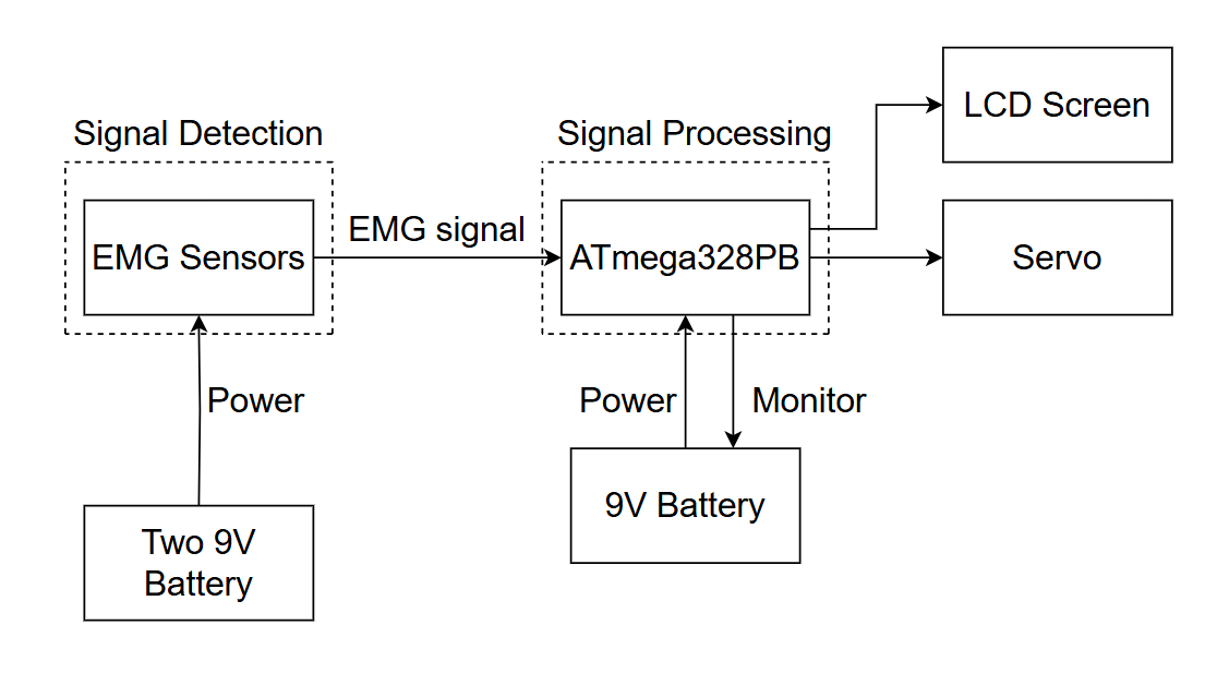
For the hardware implementation, we 3D printed the gripers and box for holding the EMG sensor, ATmega328PB, LCD screen servo, and electronic components. A voltage regulator was used to lower the 9V battery to 5 volts and supply power to the ATmega328PB. Two 9V batteries are used to power the sensor. For each of the batteries, there is a switch to turn on and off the ATmega328PB, LCD screen, and sensor. For measuring the battery percent, a voltage divider is used to scale down the battery voltage to a level that can be measured by the ADC on the ATmega328PB. About the sensor, ATmega328PB reads the data from the sensor using ADC. The button on the ATmega328PB is used to changing the mode to for selecting the type of gripper to use because each gripper has different angles to operate. The wiring diagram below shows the connection between the ATmega328PB, LCD screen, and sensor.
3. Explain your firmware implementation, including application logic and critical drivers you’ve written.
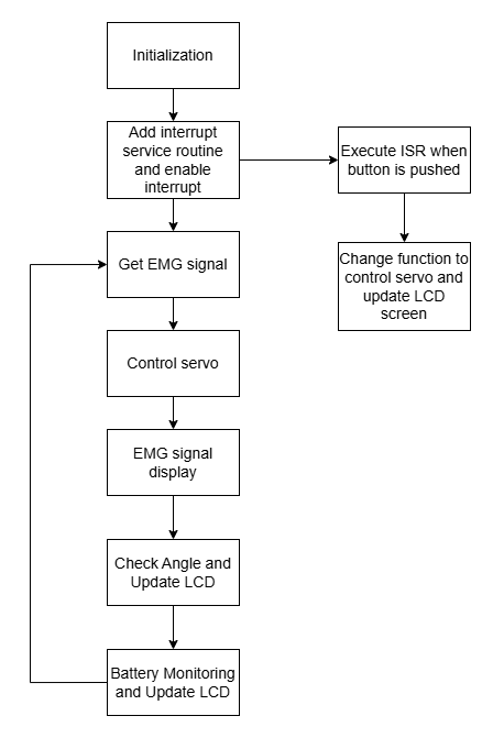
For firmware implementation, initialization is performed at the first part of the flow. The LCD screen, ADC for the battery and EMG signals, interrupt, servo, and input and output pins are initialized. After that, there is an infinite loop. At first, the data from the EMG sensor is read by using ADC. Then, the servo is controlled using the data. The EMG signal data and angle of the servo are displayed on the LCD screen. The last part of the loop is updating the battery percent. The battery is monitored by using ADC and the voltage of the battery can be measured. The voltage is converted to a percentage and displayed on the screen. The mode for selecting the type of gripper to use is changed by using an interrupt. When the button is pushed which means an interrupt occurs, the LCD screen is updated to display the current mode, and the function to control the servo is changed. One of the critical drivers of our code is the function to control the servo. The PWM mode is used to control the servo’s angle by adjusting the pulse width of the PWM signal. The other important driver is to read the EMG signal data from the sensor. The ADC is configured to read EMG signals. After that, the data is used to control the servo and display it on the LCD screen.
4. Have you achieved some or all of your Software Requirements Specification (SRS)?
There are software requirements specifications including signal processing, control logic, and user interface. The requirement for signal processing involves detecting EMG signals, filtering noise, and classifying the strength of the signals. This requirement is achieved since the value of the EMG signal was displayed on the LCD screen and if we changed how strong we held our hand, the value on the LCD screen was changed. For control logic, this requirement is to implement decision-making algorithms to open or close the claw based on EMG signal thresholds. We achieved this requirement by outcomes that if we opened and closed our hand, the servo also opened and closed. About the user interface, this requirement provides real-time feedback on signal strength and claw position. We achieve this requirement by controlling the servo to open and close immediately in response to the hand opening and closing. In addition to that, there is an LCD screen showing the EMG signal and the angle of the servo.
5. Have you achieved some or all of your Hardware Requirements Specification (HRS)?
There are hardware requirements specifications including EMG sensor, ATmega328PB board, and power supply. For the EMG sensor module, the EMG sensor must accurately detect muscle signals with minimal noise. This is achieved by displaying the EMG signal on the LCD screen, which updated correctly as we changed the strength of the muscle. The ATmega328PB board should have sufficient processing power to handle real-time signal processing. ATmega328PB correctly displayed data on the LCD screen and controlled the servo as intended. For power supply, it should meet the voltage and current requirements of all components, ideally with a margin for efficiency. We measured the voltage of each of the batteries and ensured it met the voltage and current requirements of all components. The LCD screen, sensor, and ATmega328PB were all powered on using batteries.
6. Show off the remaining elements that will make your project whole: mechanical casework, supporting graphical user interface (GUI), web portal, etc.
We still have several elements to complete in the project, and one of the key tasks involves the mechanical casework. Specifically, we need to arrange all the components inside the box in a way that secures them while ensuring proper cable management. Additionally, it’s important to design the layout to allow easy access for code updates in the future. We 3D printed the box, as shown below, but we have yet to finalize the internal placement of the components. We have to configure the components inside the box so that we can easily update the code when needed

7. Demo your device.
8. What is the riskiest part remaining of your project?
One of the riskiest parts of our project is the connections of the wires. While most of the components have been soldered, not all connections have been soldered yet, leaving some parts unstable. The lack of consistent and secure connections increases the likelihood of intermittent or faulty behavior. We plan to de-risk this issue by completing the soldering of all connections and securing connections. The other riskiest part of our project is waterproofing. It is important to protect the electronics from exposure to water and prevent any power loss that could disrupt performance. We currently have a box to hold all our components, but there are some holes that water can enter. We plan to design a waterproof enclosure that can hold all critical electronics.
9. What questions or help do you need from the teaching team?
Do we have more accurate EMG sensors?
Is there better calculation for filter the noise?
Sprint review #1
Current state of project
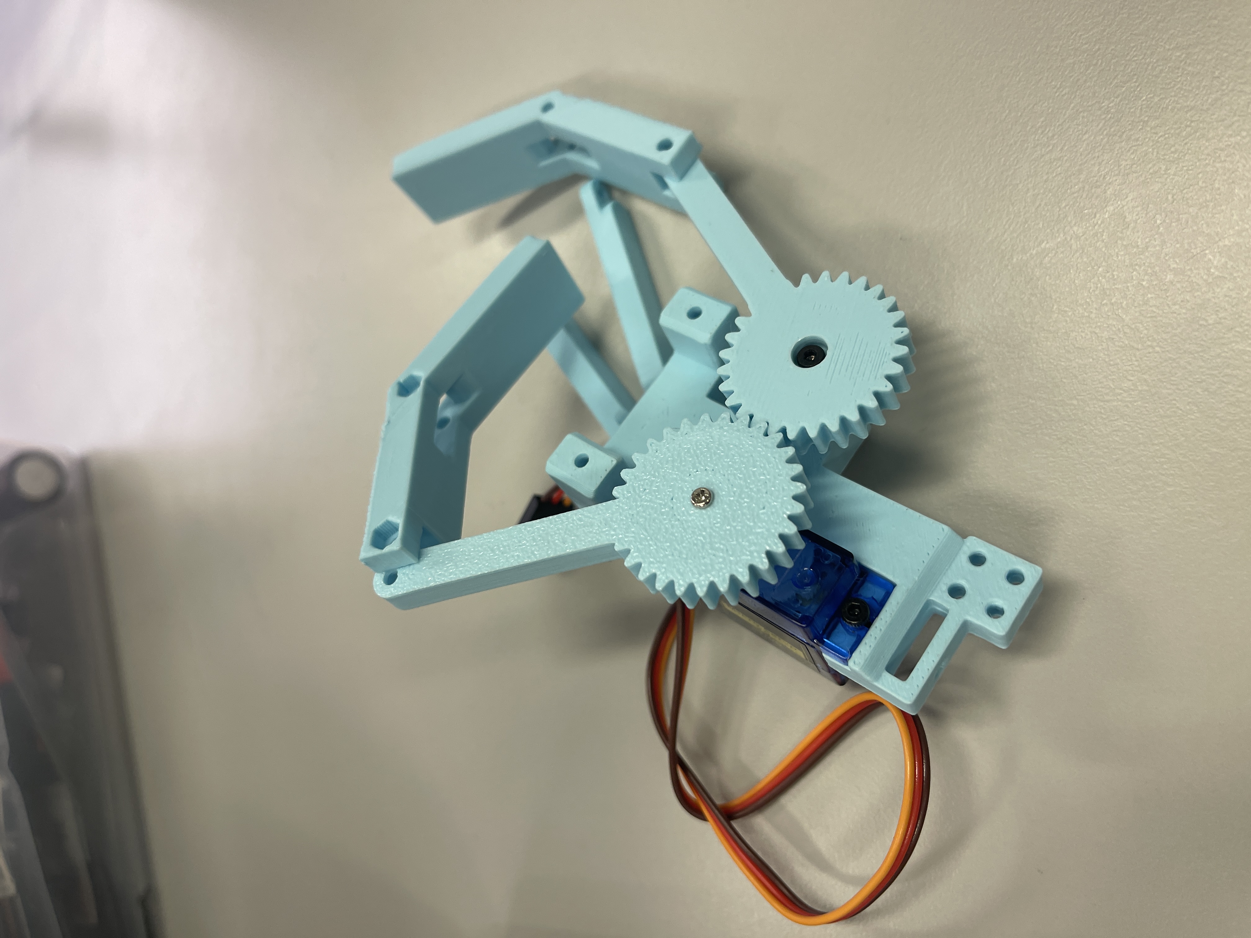
For the last week, we order the parts what we need. Also, I used the 3D printer to print the griper. I attached in next. There is an update that we cannot use the ESP 32 without the wifi or Bluttooth. So we may decide to make up out project which means we will add the app to monitor the battery or the statues of the machine.
Last week’s progress
We finish the hardware set up which is the first step of the project. Next is the testing and coding. Also, we may will make more functions in our project. Hardware status - we order the parts what we need. Printed the first gripper.
Next week’s plan
For next week, we will finalize the hardware and software requirements. We plan to add more features to monitor battery and servo using LCD. We will update hardware and software requirements as well as system architecture block diagrams and add new features. Estimated time for this is about 2 hours. We will update the github repository in the final project proposal section after we finalize the hardware software requirements and system architecture block diagram. We will start testing EMG signals and the function of the gripper. We will work on signal processing to detect EMG signals by sensors and filter noise, as well as the function of gripper to servo moves based on the EMG signals. Estimated time for this task will be about 5 hours and we will work together for this task. If servo moves based on the EMG signals, our tasks for next week will be finished.
Sprint review #2
Current state of project
We finished the 3D print and got the battery and the servo motor. Therefore, we assembled the movement components. We tested the servo with the simple code, it seems to work not very well. It might be the friction of the screw. Also, we printed another claw as output, but unfortunately, it did not work perfectly.
Last week’s progress
We finish the hardware and code test which is the second step of the project. Next is the adjust the output. Also, we may make more functions in our project. Hardware status - we have two parts that we need(the battery and the servo). Printed the second gripper.
Next week’s plan
For next week, we will mainly adjust the code and the gripper setup, but if we get the EMG sensor ,we will test it first. We plan to add more features to monitor the battery and servo using LCD. We will update the github repository in the final project proposal section after we finalize the hardware software requirements and system architecture block diagram. After we got the EMG sensor, we will start testing EMG signals and the function of the gripper. We will work on signal processing to detect EMG signals by sensors and filter noise, as well as the function of gripper to servo moves based on the EMG signals. Estimated time for this task will be about 3 hours and we will work together for this task. If servo moves based on the EMG signals, our tasks for next week will be finished.
Sprint review trial #3
Current state of project
We printed the all necessary gripper and code tests which is the “function” step of the project. Next is the adjust the output. Then, we can combine them to finish our demo. Hardware status - we finished three(the battery, 328pb, and the servo) of five(Lcd screen, 328pb board, Battery, Grippers, EMG sensor) parts that we need. Printed the all necessary grippers.
Last week’s progress
We printed two more grippers and finished the code to test the working degree of all of the grippers. Also, the battery of the origin order needs to be fixed. So, we changed the strategy to use the 9V battery. Since the sensor has not yet arrived, we just brought another form of Amazon.
Next week’s plan
Next week, we will work on testing the EMG sensors. We will test if EMG signals can be detected, processing signals to filter noise, and move the gripper by controlling the servos based on the EMG signals. Zhongkun is assigned to do this work and it is estimated to take about 5 hours to finish this work. If the gripper moves, we change the muscles signals and this means this work is completed. The second part of our plans for next week is about LCD screen functions. We plan to display EMG signals, battery, and current mode. For EMG signals, we will display if it is on or off. About the battery, the percentage of battery remaining is displayed. For the current mode, the mode is controlled by a button, and changing the mode will change which gripper is controlled because each gripper has different maximum angles to reach. Toma is assigned to do this work and it is estimated to take about 3 hours to finish this work. If all of these are displayed on the LCD screen, the work is completed.
Final Project Proposal
1. Abstract
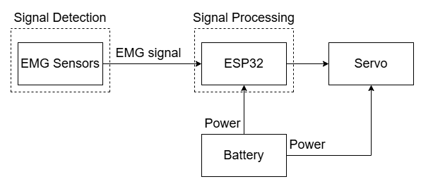
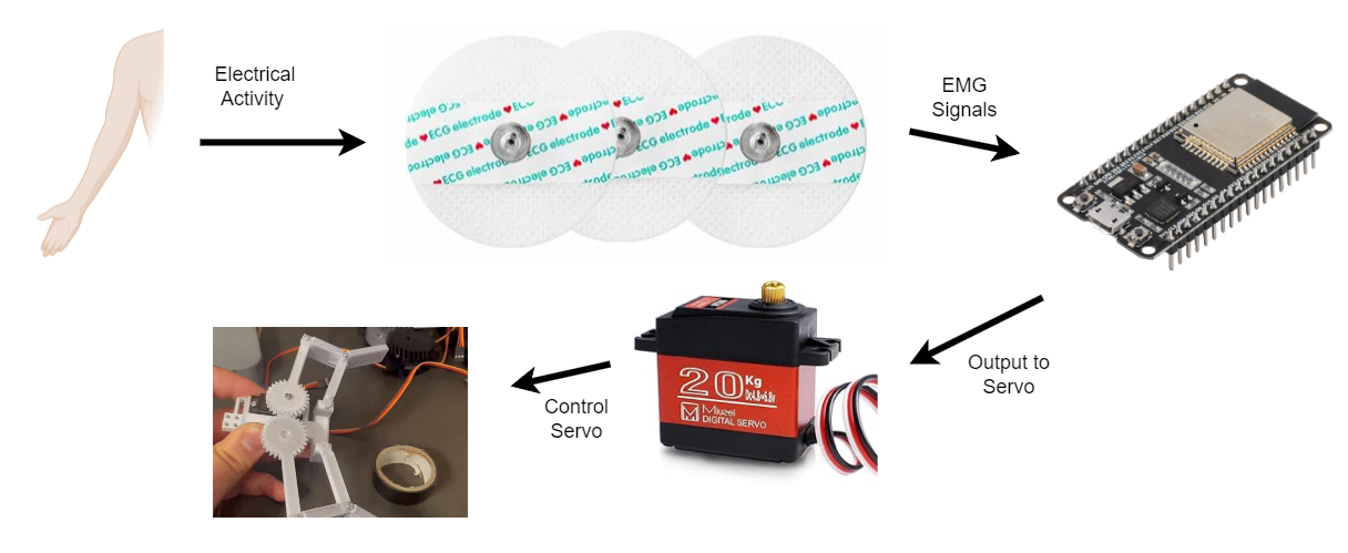
This project is to build an EMG-controlled claw which measures electrical activity produced by muscles and controls the mechanical claw. The EMG sensors detect the electrical activity from muscles and send signals to a microcontroller which we are using ESP32. The microcontroller processes the signals and controls mechanical claw by using motors or servo. This project demonstrate applications in human machine interaction, prosthetics and rehabilitation.
2. Motivation
This project attempts to solve is that people with disabilities or injuries gain the ability to perform everyday tasks that require hand movements. The interesting part of this project is that it shows the human-machine interaction, where the machine is controlled directly by using human muscle signals. Intended purpose of this project is to create a EMG-controlled claw that can help people with disabilities. People with disability can control the claw through their muscle signals, so they can grab objects or reach spots they could not reach before. Our product can enhance independence and improve the quality of life for people with disabilities.
3. Goals
One of the goals of this project is related to the EMG signals, and to detect EMG signals from muscles accurately and filter and process the raw EMG signals. The second goal is to implement control logic that can translate processed EMG signals into movement of the claw by sending signals to servo. The third goal is to design and build the claw that can perform the desired movements such as open, close, grip, and release effectively.
4. System Block Diagram
5. Design Sketches
6. Software Requirements Specification (SRS)
6.1 Overview
The software shall process muscle activity data to control a robotic claw, monitor battery levels, and display both the claw’s angle and EMG values. The software filters and interprets EMG signals, converting them into servo commands for precise movements based on muscle contractions.
6.2 Users
The primary users are individuals seeking assistive technology for enhanced mobility and control, such as those with limited hand function due to injury or disability.
6.3 Definitions, Abbreviations
- EMG: Electromyography - measurement of electrical activity produced by skeletal muscles
- LCD: Liquid Crystal Display
- PWM: Pulse Width Modulation - the technique used for controlling servo motors
- ADC: Analog-to-Digital Converter
- ISR: Interrupt Service Routine
- SPI: Serial Peripheral Interface
6.4 Functionality
SRS 01 – The software shall detect EMG signals between 0 and 1024 by ADC, filter noise under, and classify signal strength
SRS 02 – Decision-making algorithms shall open or close the claw within 0.5 seconds of detecting an EMG signal based on EMG signal thresholds, which is 200
SRS 03 - The system shall include fail-safe controls to prevent accidental or unsafe activation of the claw
SRS 04 - The system shall include the battery health calculation by ADC to show the percentage of the current battery
SRS 05 - The software will output the PWM to control the servo degree
SRS 06 - The software shall include the ISR to handle the interrupt by the button, ensuring a response time of less than 1 second.
SRC 07 - The software shall provide a user interface to display the real-time data, including EMG signal, battery health, and claw angle updating every 500 milliseconds
SRC 08 - The software shall communicate with the LCD display using SPI protocol to send data
7. Hardware Requirements Specification (HRS)
7.1 Overview
The project implements a muscle-controlled (EMG) gripper system that translates electrical signals from muscle movements into mechanical actions. The system consists of EMG sensors for signal detection, an ATmega328PB microcontroller for signal processing, a color TFT display for user feedback, and a servo motor for mechanical actuation. The system is designed to be portable and battery-powered, allowing for applications such as a gripper mechanism or Spider-Man web shooter simulator.
7.2 Definitions, Abbreviations
- EMG: Electromyography - measurement of electrical activity produced by skeletal muscles
- LCD: Liquid Crystal Display
- PWM: Pulse Width Modulation - technique used for controlling servo motors
- ADC: Analog-to-Digital Converter - for processing EMG sensor signals
- ST7735R: LCD controller chip
7.3 Functionality
HRS 01 - Project shall be based on ATmega328PB microcontroller operating at 16MHz
HRS 02 - EMG sensors (Myoware Muscle Sensor or equivalent) shall be used for muscle activity detection. The sensor shall detect muscle electrical activity in the range of 0-5V
HRS 03 - A 1.8” Color TFT LCD (ST7735R controller) shall be used for user interface
HRS 04 - System shall include a servo motor with minimum 180-degree rotation capability for mechanical actuation controlled by PWM
HRS 05 - Power supply shall be provided by a portable battery pack capable of supplying 5V DC or convert to 5V
8. Components
EMG Sensor Module: Muscle Electrical Sensor Module Muscle Analog Signal EMG Raw Signal Collection Electronic Development Kit for Arduino. Link:https://www.amazon.com/Electrical-Collection-Electronic-Development-Arduino/dp/B0CJ7FMSP4/ref=sr_1_1?crid=J0P4227VBVI2&dib=eyJ2IjoiMSJ9.wy5oWZI_jayW_Poo3osn3qHXdwVG-h-hEXhh3FzHMfljZq2Rjrobz27IfQ6mnntLpge6C3gAZN6qiC5lGZDoY8naRlNRfAVI5G7azyWi8lY.-uKuPdLkNGQc5jriVrQtQPzGzAxUYKKmLGs5I1ji89Y&dib_tag=se&keywords=Techtonics+EMG+Muscle+Sensor+Module&qid=1730060472&sprefix=techtonics+emg+muscle+sensor+module%2Caps%2C62&sr=8-1
ESP32: HiLetgo 3pcs ESP32 ESP-32D ESP-WROOM-32 CP2012 USB C 38 Pin WiFi+Bluetooth Dual Core Type-C Interface ESP32-DevKitC-32 Development Board Module STA/AP/STA+AP. Link: https://www.amazon.com/HiLetgo-ESP-WROOM-32-Bluetooth-ESP32-DevKitC-32-Development/dp/B0CNYK7WT2/ref=sr_1_1_sspa?crid=33EFNDJDTIJ36&dib=eyJ2IjoiMSJ9.kzd_BN2te2KAhw5tyJI73q7op2hMtpwF80mJByziDxVd1llDPyBKVlzIA821bZw0y1JNFZlWNCJrkRC0rY1KxzCyTqQxZFYiUqYCTS7MtkTguvd-mizF5y3c37BLoyN0MqD8gT7uujpQHL2dvY7tpnRMyu-slvRDPd6mb9K_6z-qLtKc9ssWnMF4PXNIduzTXxEgFDR6gNDyCPhOo4tJdd0AaGIVBTP–Jr4XJfWuek.njosdnREybQJ5CgvUo_1QL1ojDOzJ-d0z8PtAlPVfo4&dib_tag=se&keywords=esp32&qid=1730060568&sprefix=esp32%2Caps%2C107&sr=8-1-spons&sp_csd=d2lkZ2V0TmFtZT1zcF9hdGY&psc=1 Servos: Miuzei 20KG RC Servo High Torque Servo Motors, Waterproof Metal Gear Steering Servo for 1/8 1/10 RC Car Robot DIY, Digital Servo DS3218, Control Angle 270° (4 Pack). Link: https://www.amazon.com/Miuzei-Waterproof-Steering-Digital-Control/dp/B0CQX9SYP2/ref=sr_1_3_sspa?crid=66MWYD7AWEQX&dib=eyJ2IjoiMSJ9.1_WMN8TnuC1saC398n-qI_VAAeVcwWFhHjQTrEiHkQrmZoG1zWija-JF4VT5Co2hyDmvgmvYWIyWeROp8LT9xweX9l7yT7uUVYyVMapjdSuYW0swMYZa4iaMBTHxdcVZZ9fbSxHis_U1m1Bcpkd2ElyBZXKVGj6or5iR7A–mtkkVIqS57_JaT2n2FRp5wo6CjyL2FNofK1pmAj1wPJ_uF6S1cYca-sXZeTJjtZ5HFhS385L7BcnufJfHIBaN8SU9rEM-uxbrE3zQSnR0FgRqJtv2NNDlbAQfCq_PJvZwVs.KjItca72edBcl1-QF5SOFcJAH6Twoh84oPj-zUBHHJ0&dib_tag=se&keywords=Servos&qid=1730060626&sprefix=servos%2Caps%2C117&sr=8-3-spons&sp_csd=d2lkZ2V0TmFtZT1zcF9hdGY&th=1 Power Supply: MakerFocus 4pcs 3.7V 3000mAh Lithium Rechargeable Battery 1S 1C LiPo Battery with Protection Board Insulated Rubber Tape and Micro JST 1.25 Plug for Ar duino NodeMCU ESP32 Development Board. Link: https://www.amazon.com/3000mAh-Rechargable-Protection-Insulated-Development/dp/B08T6GT7DV/ref=sr_1_1_sspa?crid=PERXAFQX1BHW&dib=eyJ2IjoiMSJ9.9X-2MqDYbaiAXI5HS_NJ4IenTyP78Hkpb8BzyrwUTu8YioOVJI7nG80HHQ7Si5mGpW426btE-KcnfzVecIhe7BJQsV5kho-tTEAHGMbU–7hrcPRNL76W328MXiyEAtSx2YzHNmT7yaVG8_907Vswh7vfHpM99Y3I9kodwGy9oIIuKhcLsdx5r8lqkdPbuOL6Jq3T0G4LWLUpJFOgek_JkbvkoIJVt1aSd5847K-GaI.hy-AOslgjJJWhfeJrBvQiWQm3tRHyMmfnFusF5axDFE&dib_tag=se&keywords=battery+for+esp32&qid=1730060740&sprefix=battery+for+esp32%2Caps%2C104&sr=8-1-spons&sp_csd=d2lkZ2V0TmFtZT1zcF9hdGY&psc=1
Wires, Resistors, and Breadboard: Basic electronic components for circuit integration.
9. Final Demo
Topics
Timers Phase and frequency correct PWM is used to Control the Servo motor degree.
ADC ADC is used to monitor the battery health.
Power management The voltage regulator is used to convert 9V battery to 5 volts and supply power to the ATmega328PB.
Analog processing on sensor data EMG signal is detected and procssed by sensors and read by ATmega328PB using ADC.
Interrupts Interrupt is used to change the mode when the button is pressed.
Serial communication SPI is used to send data to display data on the LCD screen
Input device
Input device is the EMG sensor.
Output Device
Output device is LCD screen and servo.
Complexity
One of the difficult aspects of the project was detecting the EMG signals using sensors and filtering noise. The value which was read by sensors was noisy, and filtering the noise while ensuring accurate readings was difficult. We spent a large amount of time implementing the filtering process to obtain a clean signal suitable for controlling the servo motors by testing to place the sensors on different place on the arm. We decided to use the small muscle rather than larger muscle to read EMG signal because smaller muscle produces less noise. The other challenging part of the project was to control servo by using PWM. Servos require specific PWM signals with specific frequency and pulse width to move to precise positions and we had difficulty finding the right PWM configuration and controlling the servo.
Integration
When we integrated and put components together, we did not break anything but we had some challenges. One of the challenges was combining the servo control and EMG signal. At first, we tested separately for each of them, and we tested to ensure the servo is controlled by PWM and sensors can read data from the EMG signal from the movement of the muscle. We encountered the issue that unexpected movement of the servo sometimes. We dealt with this problem by defining the threshold for the EMG signal so that small noise cannot lead to moving the servo. Overall, it was harder to debug after we integrated all the components together since we had lots of possibilities to cause errors and had to check and fix more problems.
10. Methodology
We will start by collecting EMG data to understand the signal patterns and test it using Arduino. After developing the signal processing, we will move on to integration with the robotic gripper. Finally, calibration and fine-tuning will ensure the gripper responds appropriately to muscle input. Additionally, regular testing will verify the performance of the system.
11. Evaluation
The product’s success will be measured by: Accuracy: How well the claw’s movements correlate with intended muscle signals. Response Time: The delay between muscle activation and claw movement should be under 1 second. Stability: Consistency in claw performance over multiple tests. User Satisfaction: Ease of use and intuitiveness of the system when controlled by the user’s muscle signals.
12. Proposal Presentation
Add your slides to the Final Project Proposal slide deck in the Google Drive.
References
Fill in your references here as you work on your proposal and final submission. Describe any libraries used here.
Github Repo Submission Resources
You can remove this section if you don’t need these references.
- ESE5160 Example Repo Submission
- Markdown Guide: Basic Syntax
- Adobe free video to gif converter
- Curated list of example READMEs
- VS Code is heavily recommended to develop code and handle Git commits
- Code formatting and extension recommendation files come with this repository.
- Ctrl+Shift+V will render the README.md (maybe not the images though)