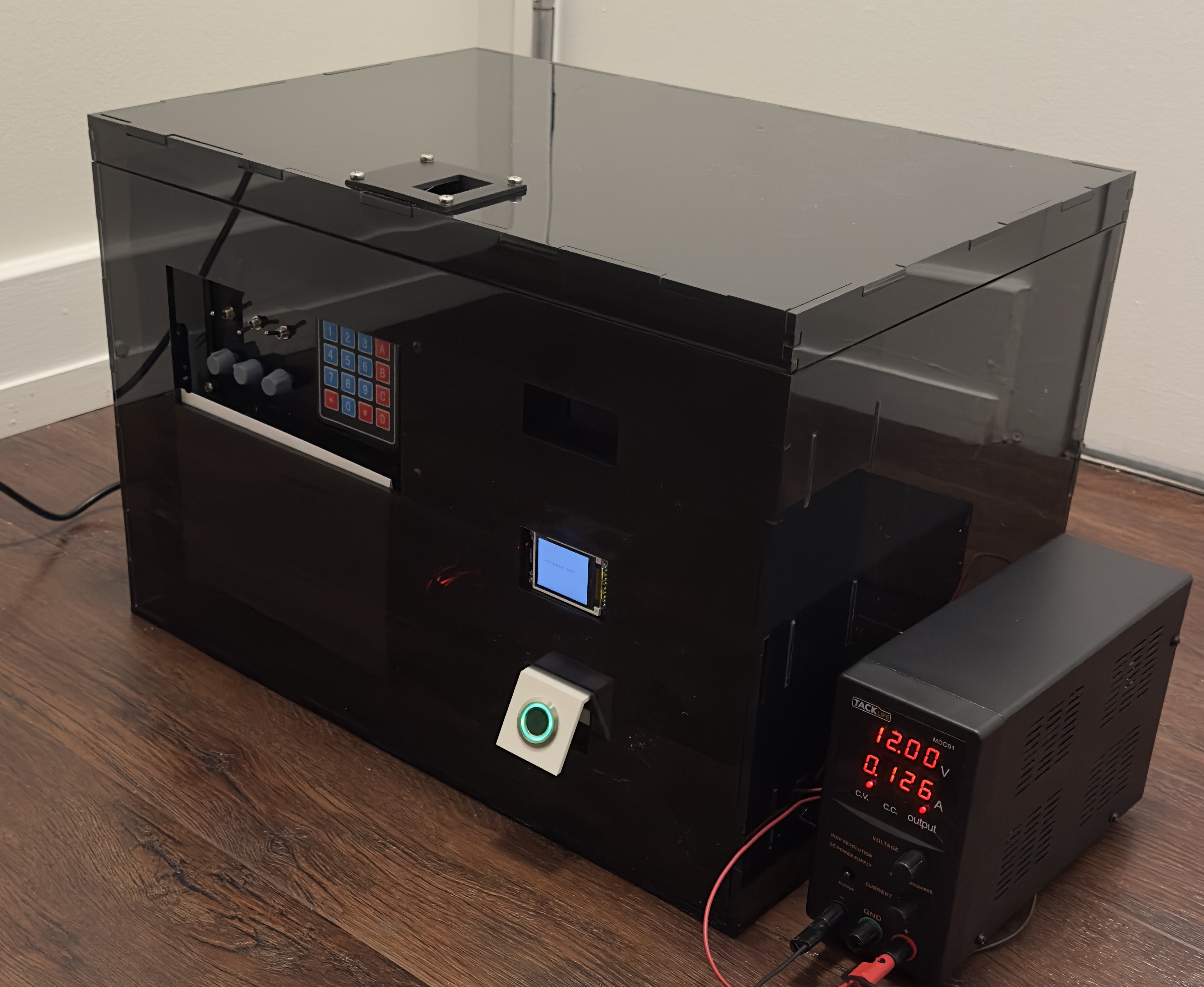
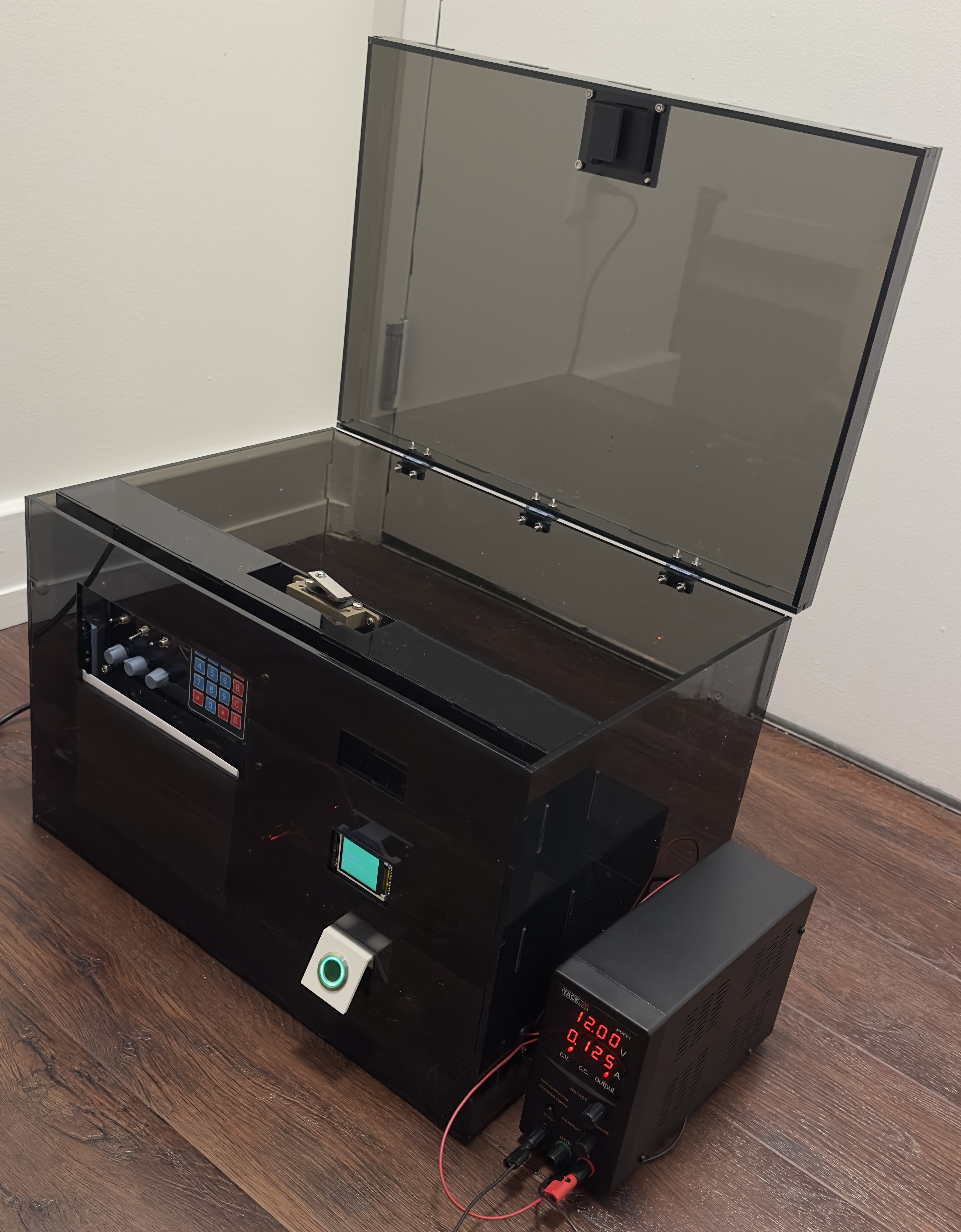
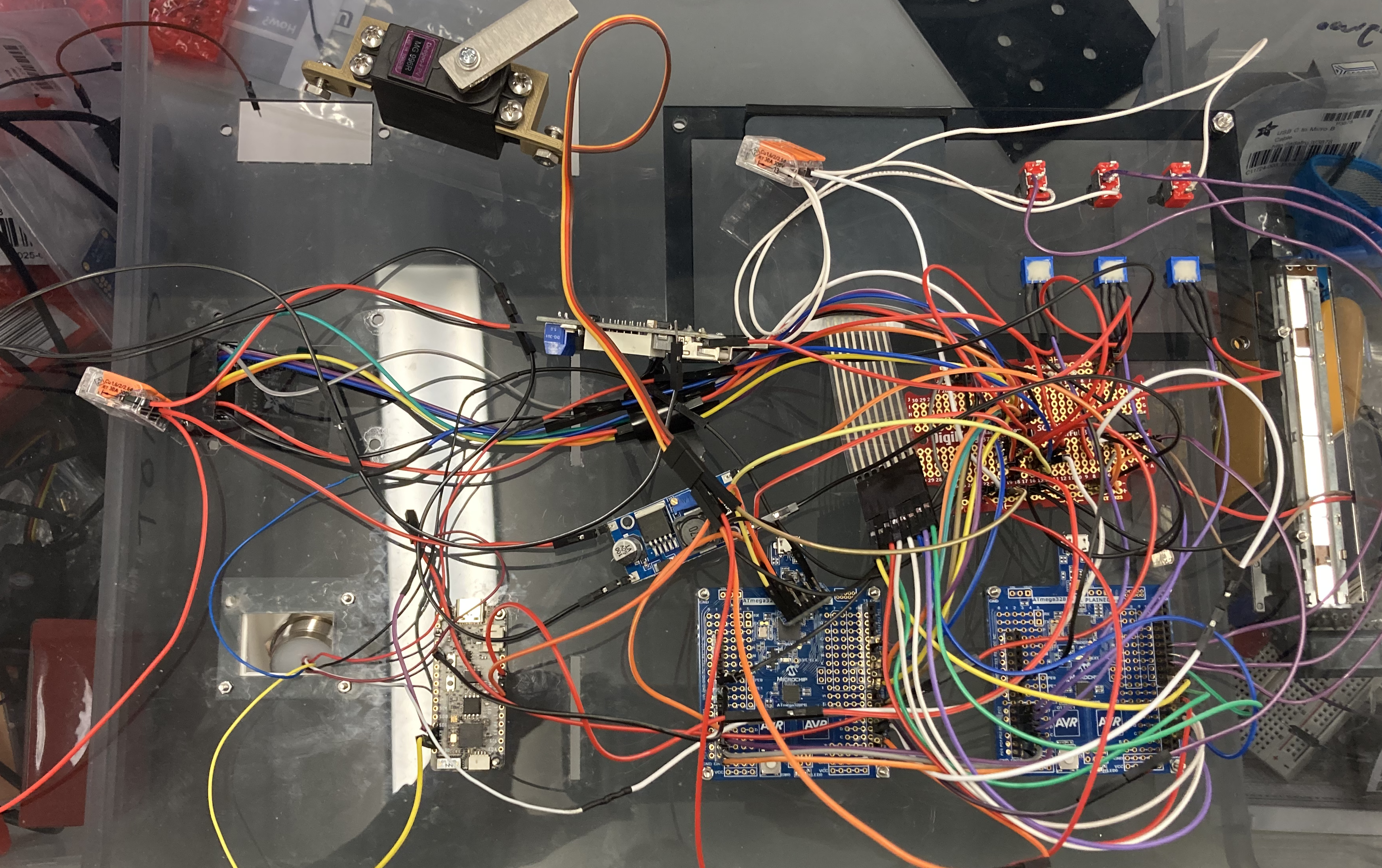
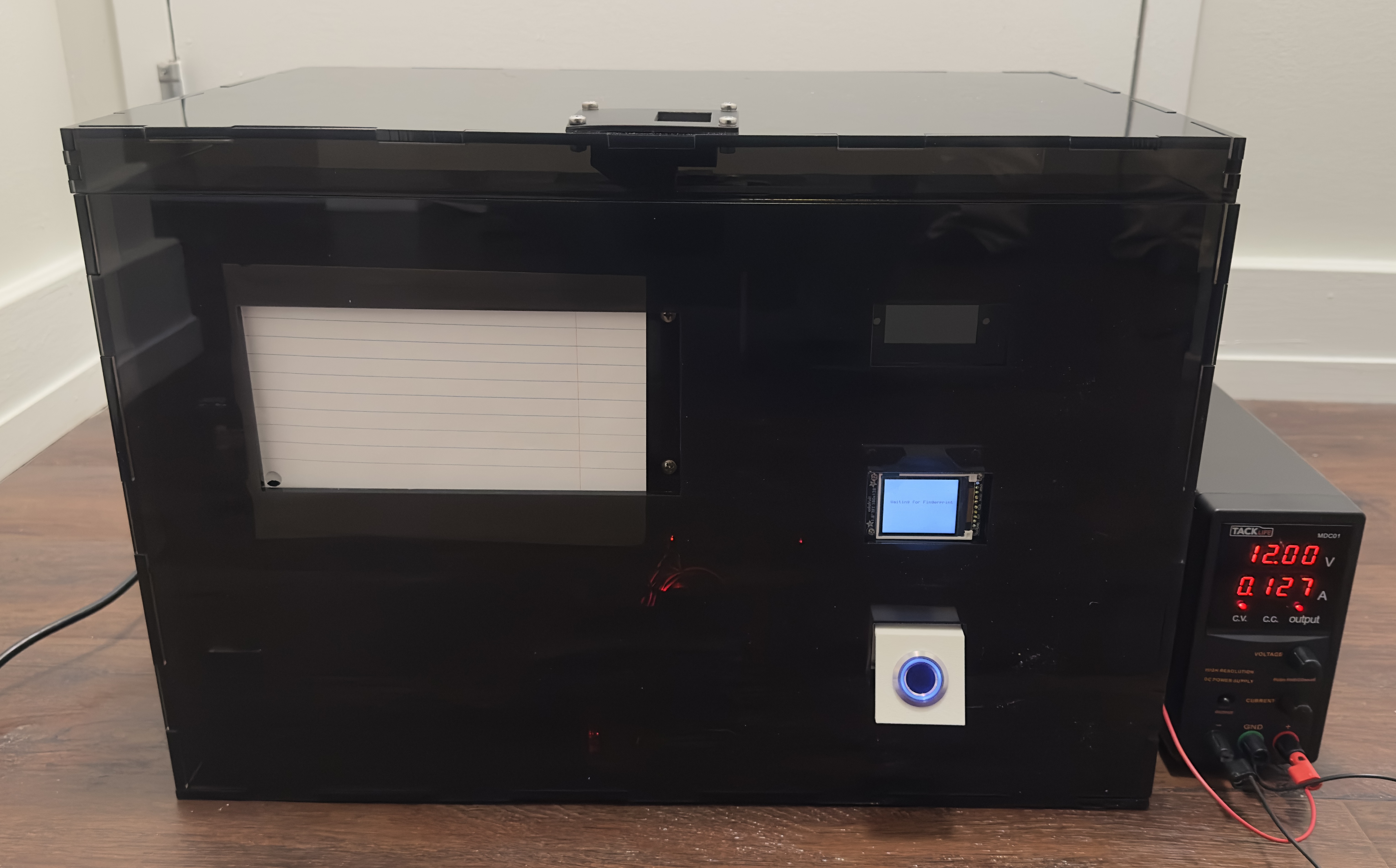
A three layer secure safe integrating biometric authentication, analog combination input, and PIN verification. Powered by two ATmega328PB microcontrollers and an ESP32 fingerprint module, Helix Vault blends embedded security logic, mechanical actuation, and a guided LCD user interface.

Device Overview
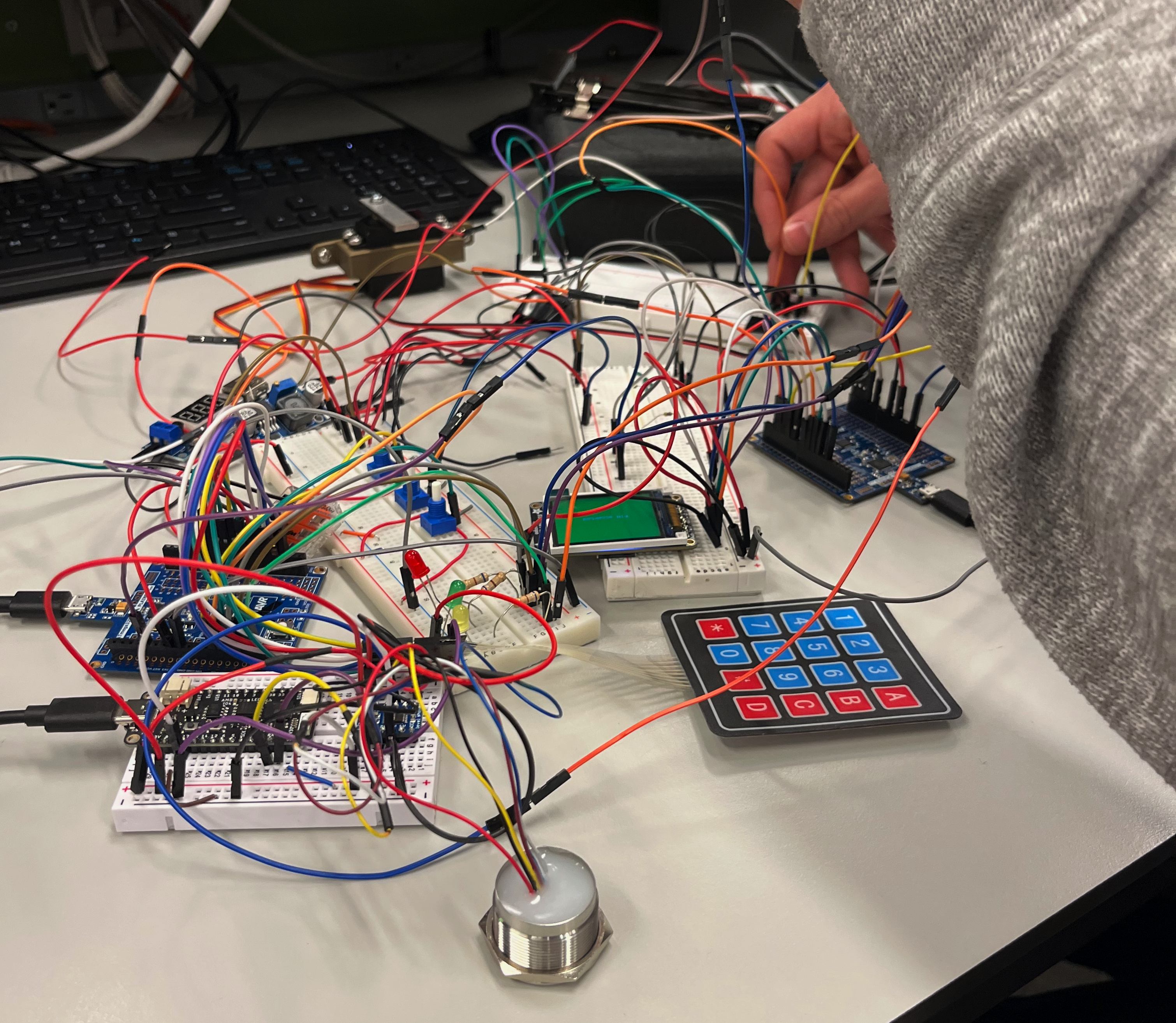
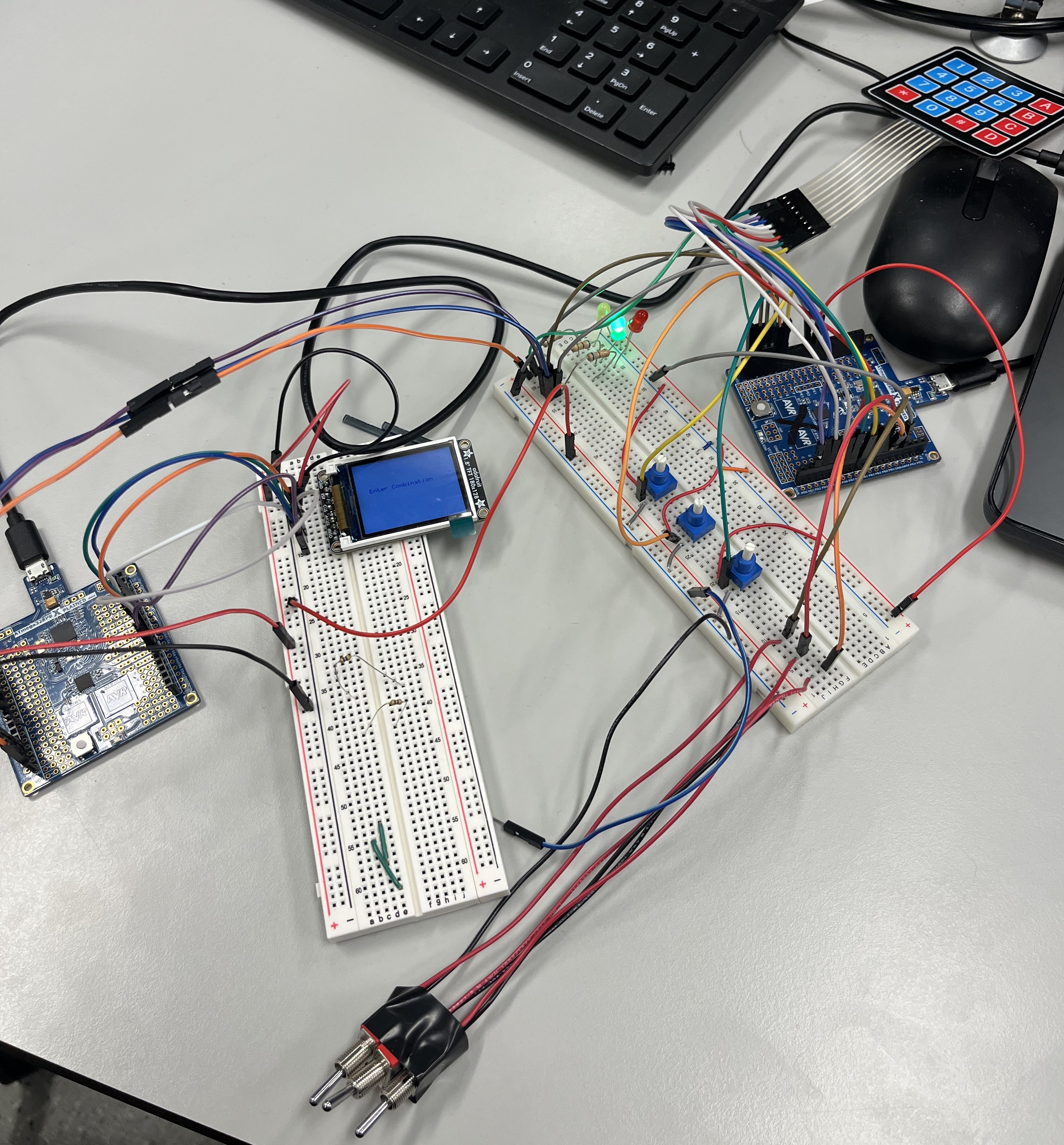
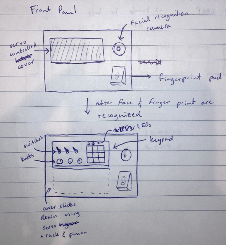
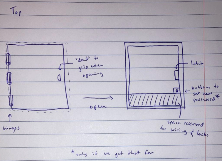
Prototype & Sketches
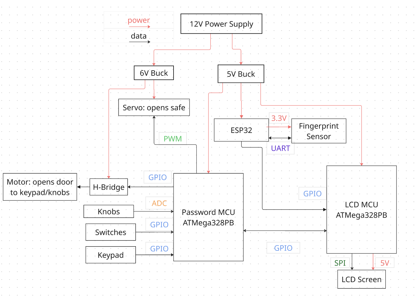
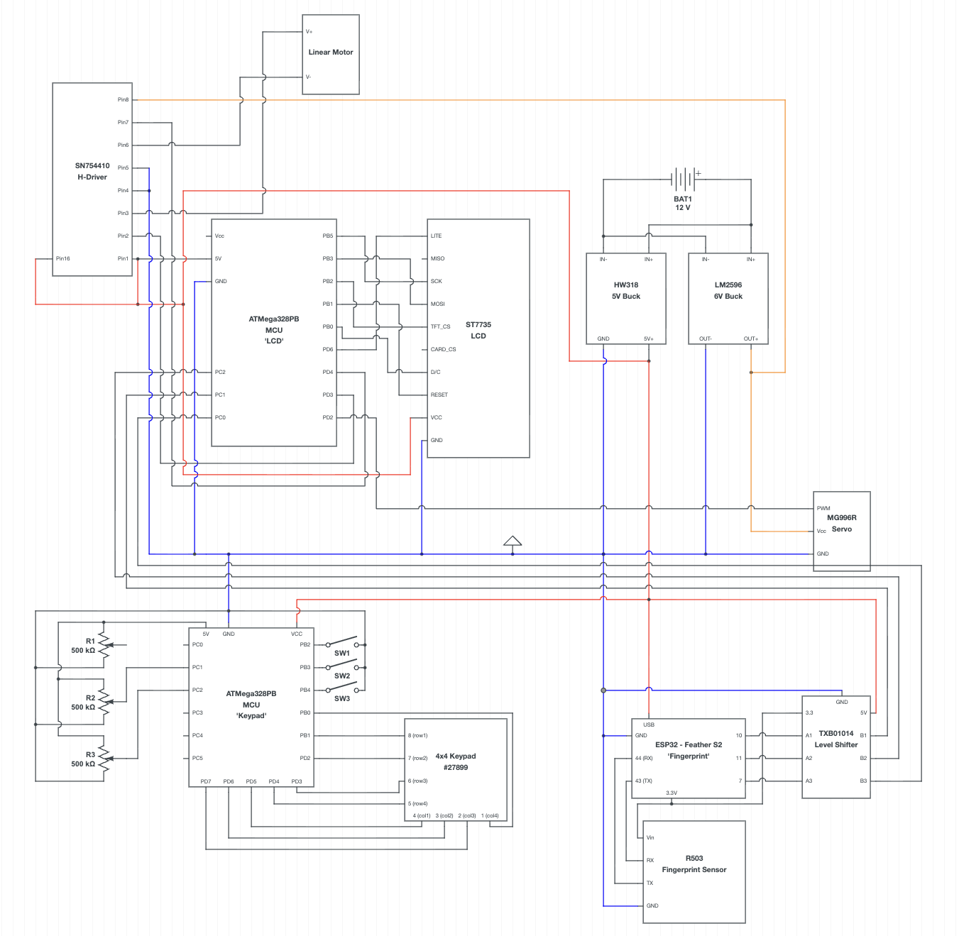
System Diagrams
Software Requirements Specification (SRS)
Low Power Management
The system shall be in low power mode when not being used. If the battery dies, it shall be rechargeable without unlocking or compromising the safe.
We did not add a low-power mode, but powering up the system never compromises safety—on startup, it always verifies that all locks are closed. If the box is powered off, it does not lock itself, so users should ensure it is closed and latched before disconnecting power. The box can also be easily locked by pressing "*", and any power loss during unlocking resets it to the first security layer.
Correct Password Recognition
The safe shall only open when the correct password is typed into the system.
Requirement fully met. The fingerprint sensor reliably accepts only saved fingerprints, each linked to a unique combination and PIN. The keypad is disabled until the analog combination is correctly entered, and only the exact 4-digit PIN associated with the authenticated fingerprint will open the box.
Servo Control
The 1st servo shall only open the door when both the facial recognition and fingerprint scans have been successful and shall close it when the user closes the box and presses the close button.
We updated this requirement to servo + DC motor control. The DC motor opens the first door only after a valid fingerprint match, and extensive testing with all of our unregistered fingers and other classmates confirmed that incorrect fingerprints never trigger it. The combination and PIN panel is physically inaccessible until this door opens, and the servo latch actuates only after the correct fingerprint, correct combination, and correct PIN are entered in sequence.
System Lockdown
The system shall lock down for 5 minutes if the user types in the incorrect password 3 times in a row.
The system does not lock down after 3 incorrect tries, but does lock down if the user "tells" it to lock down.
Storage Management
There shall be an interface for creating new passwords and deleting old ones. The system shall reject an attempt to add a new password when storage is full.
We modified this requirement, instead of having a built in interface that allows the user to change passwords and add fingerprints, this can be done using a computer and connecting to the ATMega's when the box is open and the lid protecting the electronics is taken off.
Hardware Requirements Specification (HRS)
Microcontroller
The overall system control shall be provided by the ATmega328PB.
No changes. Requirement fulfilled.
Biometric Lock 1
The first biometric lock shall be a fingerprint scanner. The fingerprint scanner shall be able to scan and recognize fingerprints from Yongwoo, Jeevan, and Tomas, and shall differentiate between them.
No changes. Requirement fulfilled.
Biometric Lock 2
The second biometric scanner shall be a facial recognition camera. This camera shall be able to scan and recognize faces, and shall differentiate between them.
Unfortunately due to shipping issues we never received the facial recognition module.
Keypad
The last lock shall be a keypad, where the user has to type an X-digit password to open the box. It shall have two LEDs: a red LED that turns on when the keypad is on but the box is closed, and a green LED that turns on when the correct password is typed in.
The keypad is used to enter a 4-digit PIN. Instead of LEDs, an LCD screen was used instead for prompting the user and showing progress.
Servo
A servo shall be used to open the door that allows the user to use the knobs and keypad. This door shall only open if the facial recognition and fingerprint recognize the user.
The door revealing the knobs and keypad is actuated by a DC motor actuating a linear slider instead of a servo. This door only opens once the fingerprint is verified.
Relay
A relay shall turn on the keypad only when the correct combination of switches and knobs is inputted.
The keypad does not need a separate power source - instead GPIO pins are used to scan for keypad inputs. They GPIOs do not scan the keypad unless the correct switch and knob combination is detected.
What Went Well
- Reliable multi-MCU communication using simple GPIO encoding
- Smooth integration of actuators with LCD-guided user experience
- Robust fingerprint performance
- Effective power management with simple 12V power supply to power all circuitry
- Mechanical design and hardware installation was seamless
- Efficiently split up tasks to create hardware and software parts that could come together for the final product
Lessons Learned
- Designing modular firmware significantly simplifies integration
- UART debugging with mis-matched voltage domains requires careful inspection
- Mechanical choices (servo torque, motor force) matter as much as code
Proudest Accomplishments
- Homemade Multi MCU communication was seamless and effective
- No broken/fried electronic components
- Extremely smooth operation and unlock process
- Final result looks very close to a final prototype
Approach Changes
- Original facial recognition stage was removed because the module never arrived
- Two servos were replaced with a DC motor + servo approach for reliability
- LEDs were replaced with a full LCD UI to satisfy SPI and improve UX
Obstacles
- Laser cutter downtime
- Hardware shipping delays
- Limited budget ($150 total)
- Low torque DC motor actuating sliding door
- Couldn't get a bare-metal C UART driver working with the fingerprint sensor
Next Steps
- Add facial recognition
- Add increased security layers
- Biometric, for example iris scanner
- More unique combination lock inputs
- Create a custom PCB to shrink the electronics footprint
- Secure override key for power failures
- Implement onboard user management
- Unlock attempt history
- With facial recognition camera pictures can be taken of the user/intruder