SMART-CHAIR

final-project-skeleton
Team Number: 21
Team Name: Team Rock
| Team Member Name | Email Address |
|---|---|
| Muhammad Noman | noman178@seas.upenn.edu |
| Deepa Lokesha | deepasr1@seas.upenn.edu |
| Ruoqi Wu | neorqi@seas.upenn.edu |
GitHub Repository URL: https://github.com/upenn-embedded/SMART-CHAIR.git
GitHub Pages Website URL: https://upenn-embedded.github.io/SMART-CHAIR/
Final Project Proposal
1. Abstract
We propose Smart Chair, a smart ergonomic chair designed to monitor sitting duration and posture quality in real time. A seat-mounted pressure sensor detects user occupancy and measures cumulative sitting time, while Time-of-Flight distance sensors on the backrest track the gap between the user’s back and the chair to assess posture states such as neutral, slouched, or leaning forward. The system is powered by an ATmega328PB microcontroller, which aggregates sensor data, executes posture analysis, and provides real-time feedback through a vibration motor and a speaker.
In addition, the chair includes an adjustable sitting timer that allows users to set custom sitting durations. When the preset time is reached, the system notifies the user through audio alerts. This feature encourages users to take timely breaks and maintain healthy sitting habits. The project aims to promote long-term ergonomic awareness and reduce sedentary health risks through simple, data-driven feedback mechanisms.
2. Motivation
In today’s digital world, IT professionals and individuals who spend prolonged hours working at desks often face health issues due to a sedentary lifestyle. Extended sitting durations and incorrect posture can lead to musculoskeletal problems, fatigue, and long-term health concerns.
This project is motivated by the need to promote a healthier and more active work routine among desk workers. By addressing both inactivity and poor posture, the project encourages users to take regular breaks and maintain correct sitting habits.
The primary objective of this project is to develop a system that monitors a user’s sitting posture and activity duration. The system alerts the user when poor posture is detected and reminds them to take short breaks, for example, a five-minute walk after every thirty minutes of sitting. The intended purpose is to help users stay active, prevent posture-related health issues, and maintain overall physical well-being during long working hours.
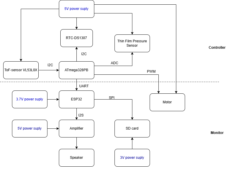
3. System Block Diagram
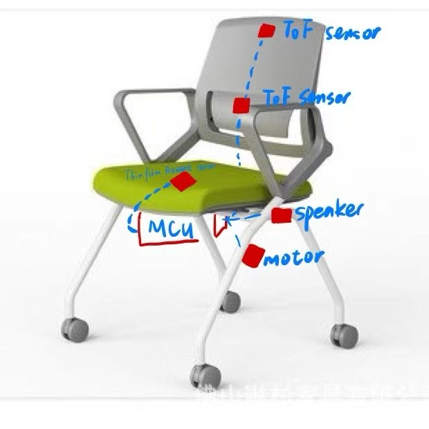
4. Design Sketches
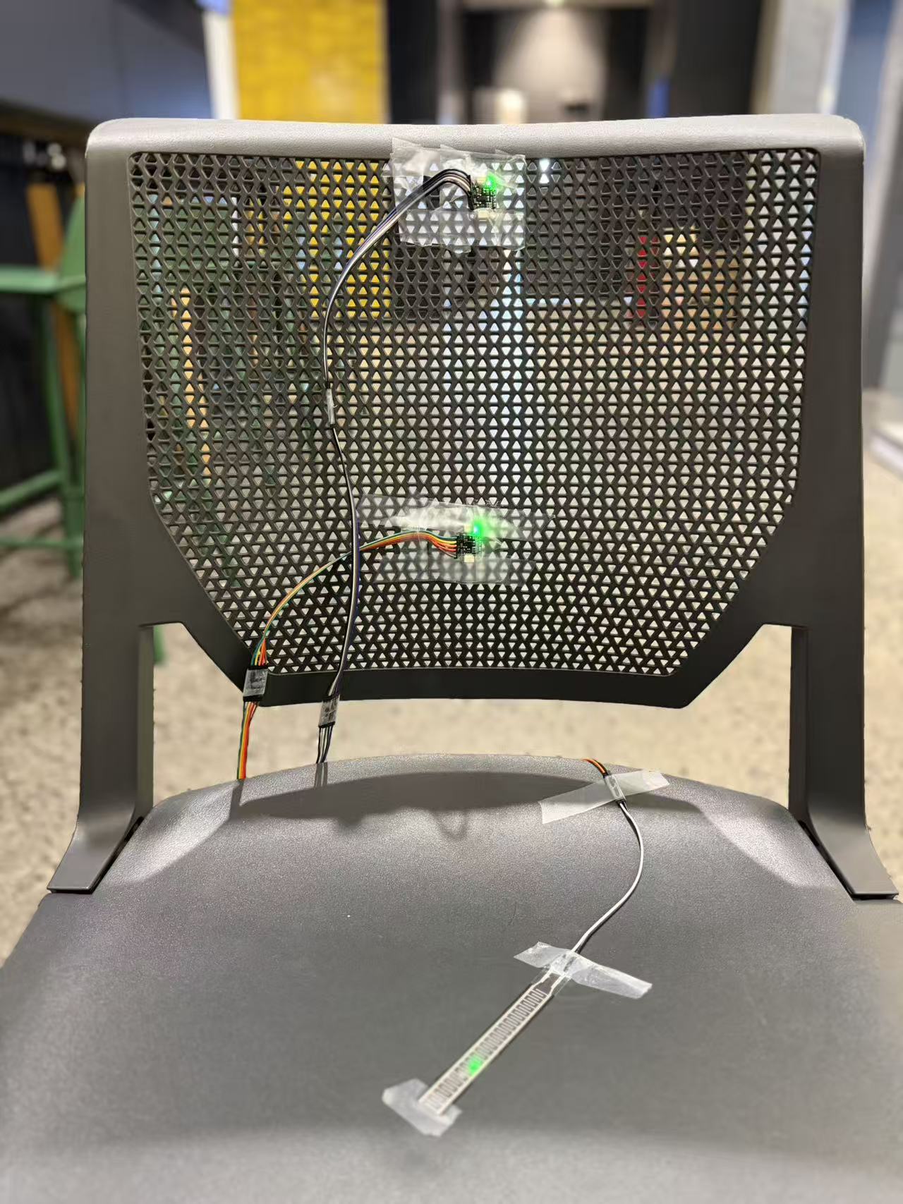
This Smart Chair will be constructed by integrating sensing and control modules onto a chair frame. This system includes three functional parts: a seat sensing part, a backrest sensing part, and a feedback and control part.
- Seat Section: One pressure sensor is installed on the seat cushion to detect user occupancy and measure sitting duration.
- Backrest Section: Two Time-of-Flight distance sensors are mounted on the backrest to measure the distance between the user’s back and the chair surface, allowing the system to classify posture states such as neutral, slouched, or leaning forward.
- Control and Feedback Module: The MCU collects data from all sensors, processes the readings, and controls the feedback mechanisms. The vibration motor and the music from the speaker alerts the user.
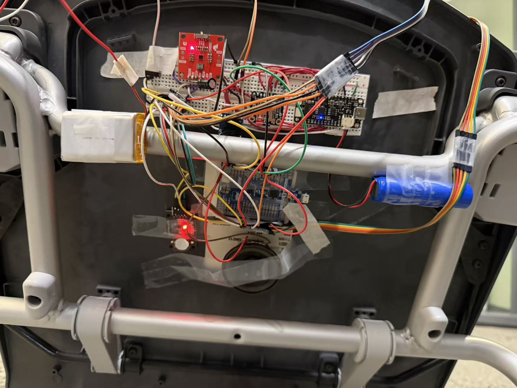
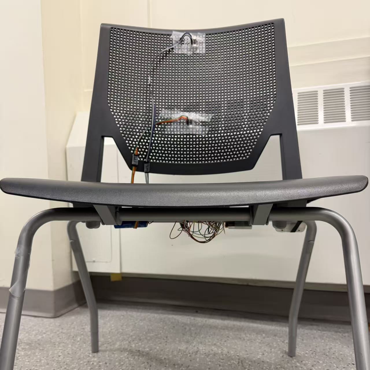
The Smart Chair is designed with a compact and ergonomic structure that prioritizes comfort, functionality, and ease of assembly. All electronic wiring is routed internally along the chair frame to ensure user safety and maintain a clean, professional appearance. The system adopts a modular layout, allowing individual components such as the sensors, control board, and power supply to be easily maintained or replaced.
Sensor mounting brackets are adjustable to accommodate users of different heights and body types, ensuring accurate posture detection. The system operates safely at 5V, providing low power consumption and easy portability for demonstrations.
For manufacturing, only basic hand tools such as screwdrivers, drills, and adhesive mounts are required. Some structural components, such as brackets and enclosures, may be fabricated from lightweight aluminum or plastic using 3D printing to achieve precise fitting and improved durability.
5. Software Requirements Specification (SRS)
5.1 Definitions, Abbreviations
Pressure Sensor Data Sampling: Refers to reading analog force data from one thin film pressure sensor via ADC channels connected to the MCU. Each sensor uses an inverting op-amp conditioning circuit to convert variable resistance into measurable voltage (0-5V range). The ADC samples the sensor channel to detect seat occupancy, measure force distribution, and track cumulative sitting duration.
ToF Distance Measurement: Refers to communication with two Time-of-Flight distance sensors over the I²C interface to measure the distance between the user’s back and the chair backrest.
Vibration motor and speaker :Are controlled by the MCU’s digital outputs and driver circuits to provide haptic and auditory alerts triggered by detected poor posture.
ESP: Conducted over a UART interface to receive posture and seating duration data to control external amplifier for alerting user through audio.
5.2 Functionality
| ID | Description |
|---|---|
| SRS-01 | The system shall read analog data from one thin-film pressure sensors using the MCU’s ADC , updating seat-occupancy status and sitting-duration counters every 200ms . A user shall be considered “absent” if all sensor readings remain below a calibrated no-load threshold for more than 1s . |
| SRS-02 | The system shall communicate with two ToF distance sensors over I²C and request distance data . |
| SRS-03 | The vibration motor shall be controlled via GPIO digital outputs with a reaction latency of 5s from the posture detection event. The duty cycle of the GPIO signal (PWM) shall be adjustable to provide variable haptic intensity. |
| SRS-04 | The speaker shall be controlled via GPIO digital outputs to emit an auditory alert with a reaction latency of <200ms. The output shall support configurable tone or voice prompts, with the volume level maintained within a safe, non-startling range. |
| SRS-05 | The ESP shall transmit posture and sitting-time data via UART. |
| SRS-06 | The system shall communicate with one RTC over I²C to get the time data. |
6. Hardware Requirements Specification (HRS)
6.1 Definitions, Abbreviations
Pressure Sensor: Provides seat pressure readings used by the software to detect user occupancy and calculate cumulative sitting duration.
ToF (Time-of-Flight distance sensor): Measures back-to-backrest distance to estimate posture states such as neutral, slouched, or leaning forward.
MCU (Microcontroller Unit): ATmega328PB processor running firmware that aggregates sensor data, executes posture logic, and controls system outputs.
Vibration motor and speaker:Used to alert the user reagrding bad posture and seating duration.
ESP: Module used for transmitting posture and tracking user sitting time.
6.2 Functionality
| ID | Description |
|---|---|
| HRS-01 | The system shall include one thin film pressure sensor mounted on the chair supports to detect seat occupancy and weight distribution. The sensor shall accurately detect loads from 0–50kg . |
| HRS-02 | Two ToF distance sensors shall be mounted on the backrest to measure the distance between the user’s back and the chair. Each sensor shall operate within 20–1200mm range and maintain accuracy within ±1cm. |
| HRS-03 | The vibration motor shall be securely mounted beneath the chair to provide effective haptic feedback. It shall draw a maximum current of around 150mA at 3.7V and be capable of generating a noticeable vibration across the chair back seat. |
| HRS-04 | The ATmega328PB microcontroller shall process sensor data, perform posture classification, control output components, and manage timer functions. Operating voltage shall be 5V, and total current consumption shall not exceed 150mA. |
| HRS-05 | The speaker shall provide clear auditory alerts for posture correction and timer alerts. It shall have a volume output of approximately 9dB gain and require an amplification circuit with a peak current draw of <650mA at 3.7V. |
| HRS-06 | The ESP communicates with the Atmega alerting the user for bad posture via speaker. |
7. Bill of Materials (BOM)
We need 1 microcontroller that control the inputs/outputs on both controller and monitor side. We will use ATmega328PB and then an ESP module to communicate between these two boards. This ESP module will use UART protocol to communicate with the ATmega. One ATmega is used as controller and has a thin film pressure sensor and Time of Flight sensors connected to it. Thin film pressure sensor will measure the weight of the person sitting on the chair and will determine their position (if they are leaning to a side or not). The pressure sensor produce very small voltage in response to weight put on them. The other ATmega board has a vibration motor and a speaker connected to it. The vibration motor is driven using a motor driver to provide haptic feedback, while the speaker provides an auditory alert if the posture is not correct for a long interval of time. Each component used is mentioned in the BOM along with their manufacturer and link to their webpages.
8. Final Demo Goals
On demo day, our team will demonstrate the Smart Chair, a standalone ergonomic monitoring system designed to detect sitting duration and posture quality in real time. The system will be mounted on a standard chair, requiring no wearable components or external devices. The demonstration will be conducted indoors in a classroom or lab environment.
One team member will act as the seated user and perform several posture changes. The system’s pressure sensors detect when the user is seated, and Time-of-Flight (ToF) distance sensors on the backrest measure the gap between the user’s back and the chair. The system will trigger immediate feedback if an incorrect posture is maintained for too long, using the vibration motor for haptic feedback and the speaker for an auditory alert.
The demo will also include the adjustable sitting timer feature, where a custom duration (e.g., 2 or 3 minutes) can be preset. Once the preset time expires, the system will trigger a loud audio alert via the speaker and a strong vibration via the vibration motor, demonstrating the chair’s ability to encourage timely breaks.
Physical and environmental constraints: The Smart Chair operates on a 3.7V battery and requires only a stable indoor setup. A brief 30–60 s zero-calibration will be performed before the demo. The speaker alarm volume is limited to below 65dB to ensure safe operation. The entire demonstration will last approximately 5–7 minutes.
9. Sprint Planning
Project Sprint Plan
Sprint #1 - Hardware setup & basic sensing
Functionality Achieved
- Assemble the chair frame and mount 1 × thin film pressure sensor at the seating surface
- Interface the thin film pressure sensor with the ATmega328PB
- Connect and read VL53L0X Time-of-Flight sensors (upper + lower) via I2C
- Calibrate the thin film pressure sensor and baseline ToF distance measurements
Distribution of Work
- Hardware Lead : Mount thin film pressure sensor, wiring, and power regulation
- Firmware Lead : Bring-up VL53L0X code, verify serial outputs
- Testing Lead : Verify stable readings and calibration repeatability
Sprint #2 - Data fusion & posture classification
Functionality Achieved
- Implement occupancy + posture detection
- Provide haptic feedback via vibration motor
- Provide auditory alerts through speaker
-
Enable UART data transmission for posture status and sitting-time monitoring.
Distribution of Work
- Firmware Lead : Develop posture algorithm
- Communication Lead : Configure UART communication and test serial logging
- Testing Lead : Validate threshold accuracy and response time
MVP Demo - Minimum Viable Product ready Functionality Achieved
- Assemble the chair frame and mount 1 × thin film pressure sensor at the seating surface
- Interface the thin film pressure sensor with the ATmega328PB
- Connect and read VL53L0X Time-of-Flight sensors (upper + lower) via I²
- Calibrate the thin film pressure sensor and baseline ToF distance measurements
Distribution of Work
- Hardware Lead: Mount pressure sensor, wiring, and power regulation
- Firmware Lead: Bring-up VL53L0X code, verify serial outputs
- Testing Lead: Verify stable readings and calibration repeatability
Final Demo - Full polished prototype Functionality Achieved
- Implement occupancy + posture detection (neutral, slouched, forward)
- Integrate vibration motor driver (haptic feedback)
- Integrate speaker output for auditory alerts
- Enable ESP module for communication setup .
Distribution of Work
- Firmware Lead: Develop posture algorithm and implement haptic/auditory alert logic
- Communication Lead: Configure ESP module and test basic data transmission
- Testing Lead: Validate posture detection threshold accuracy and system reaction latency
This is the end of the Project Proposal section. The remaining sections will be filled out based on the milestone schedule.
Sprint Review #1
Last week’s progress
During this sprint, our primary objective was to identify a suitable chair for implementing our posture-tracking product. We began by evaluating the chairs in the Ketterer Lab; however, they did not meet our required specifications. These chairs had wheels, and the height of the backrest was not long enough to support a proper headrest, making them unsuitable for accurate head-to-neck posture measurement. We then examined the chairs in the Chemistry Library. Although the backrest length there was slightly better, the chairs also had wheels, and their structure did not allow us to properly attach our product. Additionally, since these chairs belonged to the office, we were uncertain whether we were allowed to experiment or make modifications on them. Considering these constraints, we decided that the most feasible option for now is to implement our product on a standard chair with no headrest and no wheels. While measuring the headrest area would provide more comprehensive posture data from the neck to the head, due to time and budget limitations, we have opted to focus solely on back posture measurements in this phase. This approach enables us to progress efficiently while maintaining the core functionality of our prototype.
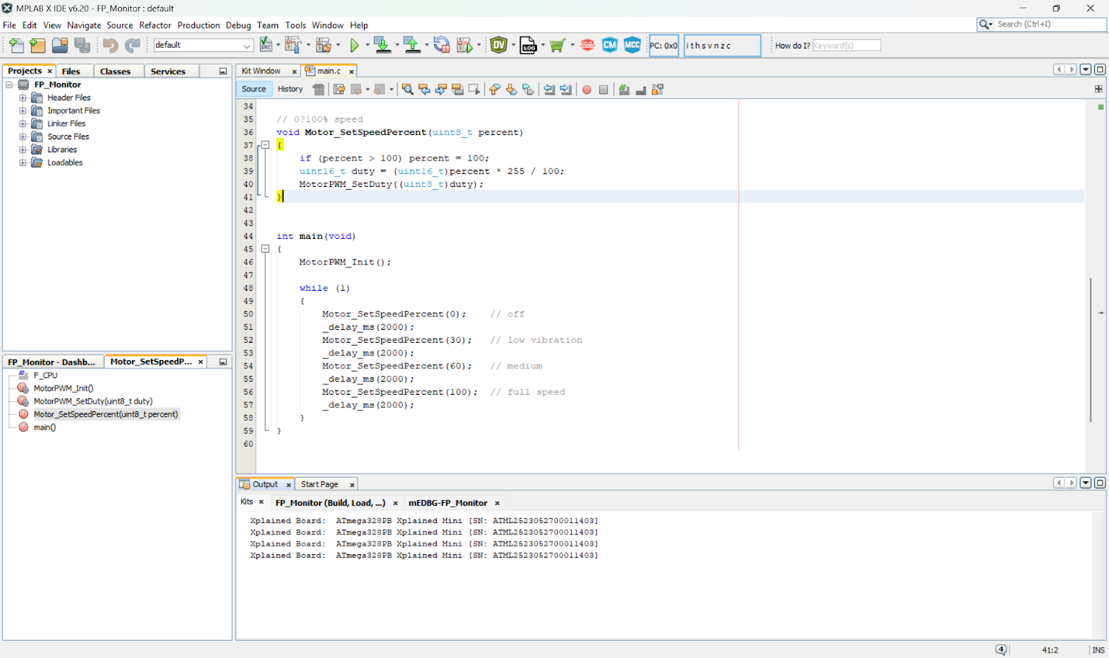
For the monitoring part of the project, we successfully met the defined objectives and made substantial progress toward the functional prototype. The vibration motor subsystem has been fully validated: we conducted comprehensive testing across the entire operating range (0% to 100%), and the motor responded reliably to PWM duty-cycle adjustments. This confirms that our speed-control implementation using pulse-width modulation is functioning as intended and delivers smooth, variable vibration intensity. Here is the link to the vibration motor demo.
The motor is controlled by varying the PWM duty cycle in the main loop. Here is the screenshot of the code which controls the motor speed.
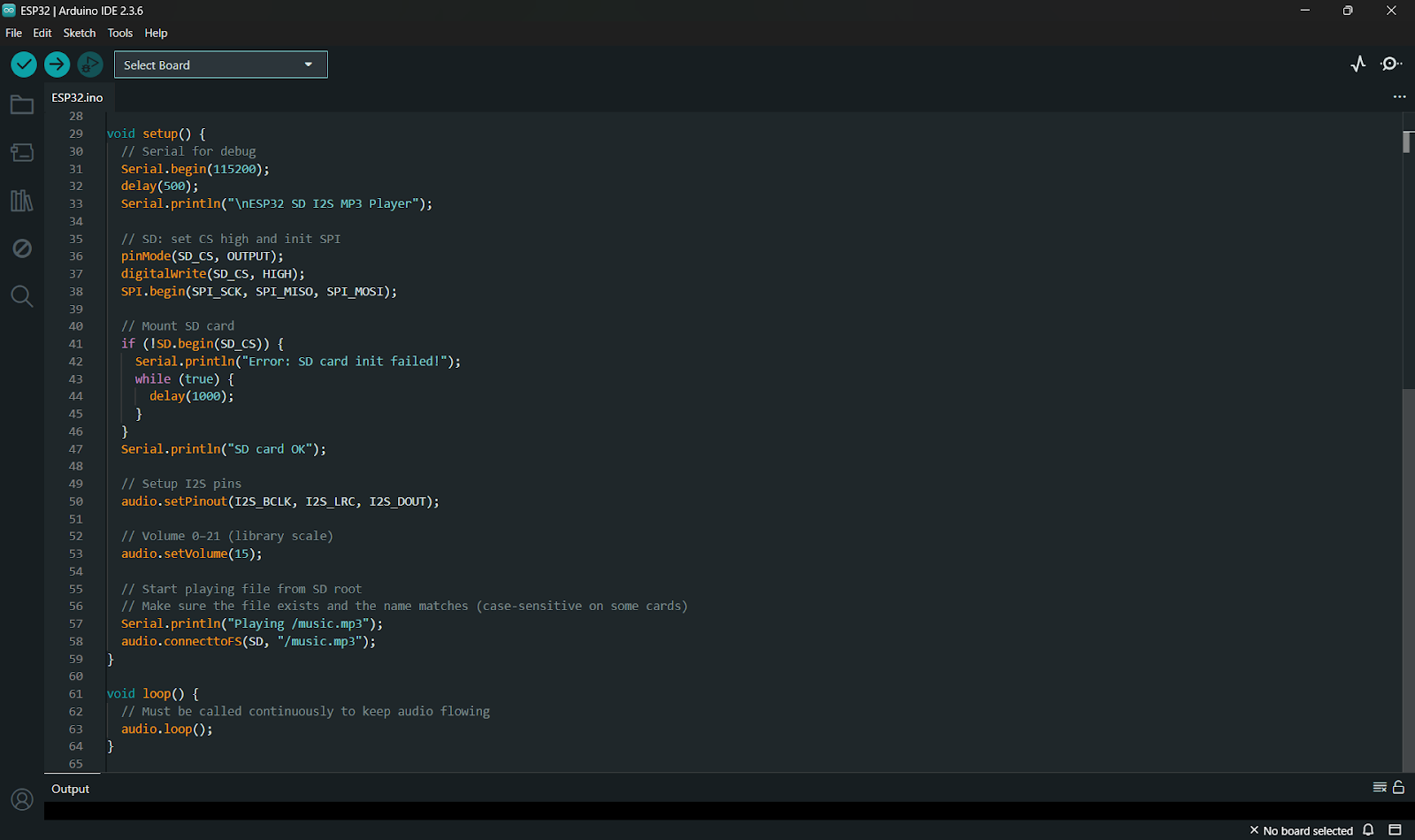
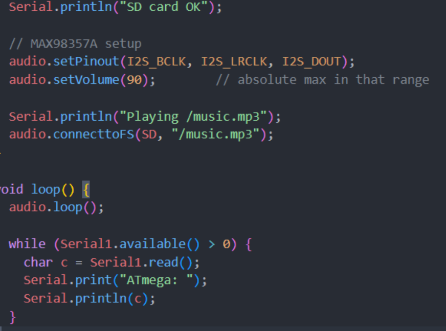
In parallel, we completed the initial development of the ESP32-based music playback module. The foundational firmware for audio control which is responsible for initializing the I2S interface and preparing the system to read MP3 files has been written and verified at the code level. However, hardware testing could not be executed because the speaker amplifier module only arrived today. As a result, full end-to-end validation of the audio playback pipeline (ESP32 to I2S amplifier to speaker) will be carried out in the next sprint. The screenshot of code for basic ESP32 music control is attached here.
Additionally, the SD card interface which is required for accessing MP3 files has not yet been tested due to pending delivery of the SD card reader module. The audio files have already been prepared and stored on the SD card, and integration testing will begin as soon as the SD interface hardware is available and connected to the ESP32.
Also, our another primary objective was to identify a suitable chair for implementing our posture-tracking product. We began by evaluating the chairs in the Ketterer Lab; however, they did not meet our required specifications. These chairs had wheels, and the height of the backrest was not long enough to support a proper headrest, making them unsuitable for accurate head-to-neck posture measurement. We then examined the chairs in the Chemistry Library. Although the backrest length there was slightly better, the chairs also had wheels, and their structure did not allow us to properly attach our product. Additionally, since these chairs belonged to the office, we were uncertain whether we were allowed to experiment or make modifications on them. Considering these constraints, we decided that the most feasible option for now is to implement our product on a standard chair with no headrest and no wheels. While measuring the headrest area would provide more comprehensive posture data from the neck to the head, due to time and budget limitations, we have opted to focus solely on back posture measurements in this phase. This approach enables us to progress efficiently while maintaining the core functionality of our prototype.
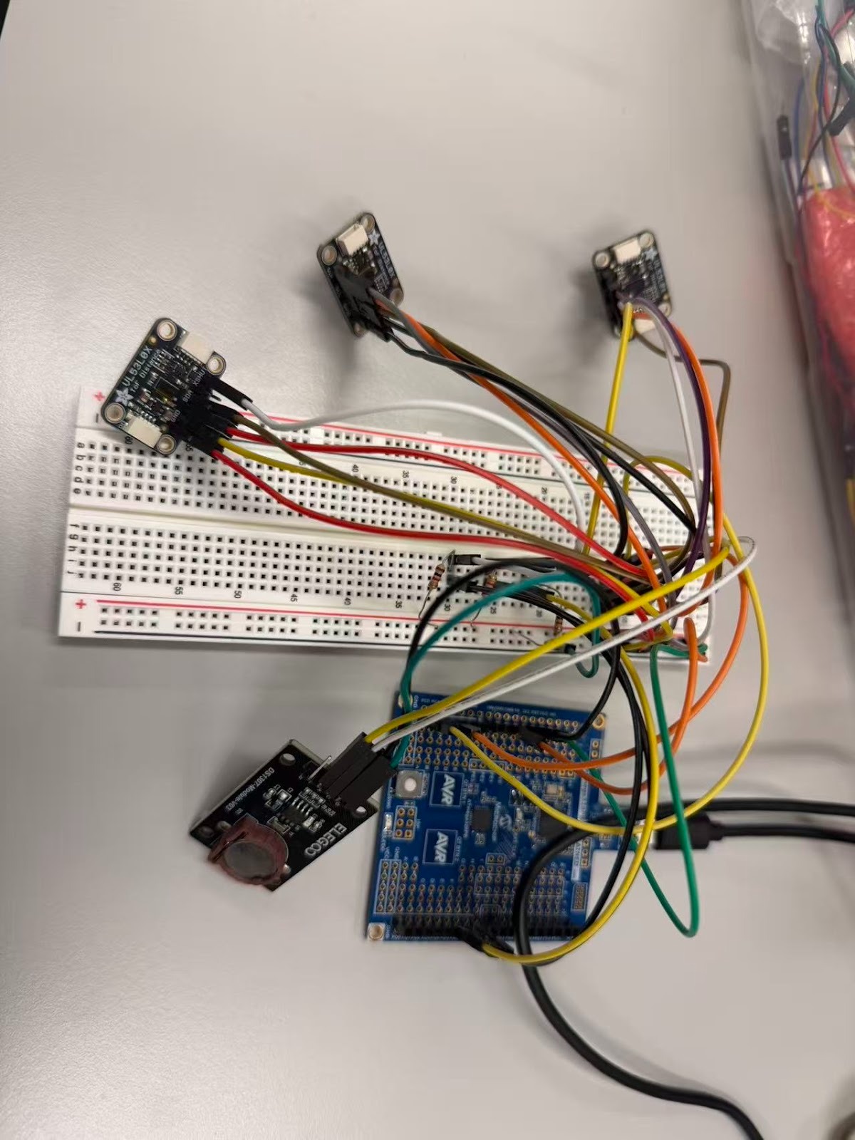
We completed the wiring and initial bring-up of the VL53L0X Time-of-Flight distance sensor. The sensor is now connected to the ATmega328PB microcontroller through the I²C interface. After running an I²C address scan, the microcontroller successfully detected the VL53L0X at its default address, confirming that both the power supply and communication wiring were done correctly. At this stage, the communication check has been completed. The next step will be writing the firmware to initialize the VL53L0X and begin retrieving actual distance readings to verify that the output is stable enough for posture classification.
Overall, Sprint 1 successfully delivered all achievable targets within the constraints of hardware availability, and the system is now well-positioned for complete audio integration and testing in the upcoming sprint.
Current state of project
The vibration motor subsystem is fully functional and has been successfully tested across the full PWM range, confirming smooth and reliable speed control. The initial ESP32 audio firmware—including I2S setup and MP3 handling—has been completed, but hardware-level testing is still pending due to the recent arrival of the amplifier and the not-yet-delivered SD card reader. Once the remaining hardware is connected, full audio playback and SD card integration will proceed in the next sprint.
For the sensing subsystem, the VL53L0X distance sensor has been fully wired to the ATmega328PB, and I²C communication has been verified through an address scan. The sensor is detected at its default address, indicating that the electrical connections, pull-ups, and power configuration are correct. The next step will be initializing the sensor, configuring timing budgets, and collecting real measurement data to evaluate stability and suitability for posture detection.
We do not expect major issues, but the delay means that multi-sensor integration and pressure sensors testing will need to be pushed into next week. The project is slightly behind the original hardware schedule but still manageable.
Next week’s plan
| Task | Assigned Member | Definition of Done |
|---|---|---|
| Implement continuous distance-reading + UART logging for debugging | Ruoqi Wu | Continuous measurements stream through UART without dropout |
| Initialize VL53L0X firmware and configure timing budget + measurement modes | Ruoqi Wu | Sensor initializes correctly and returns consistent single-reading measurements |
| Integrating PIR sensor and designing of Pressure sensor | Deepa Lokesha | The PIR sensor detects the presence of the human |
| Initial bring-up of ESP32 Music Control | Muhammad Noman | Plays basic music tones |
| Verifying stable operation of the vibration motor, ESP32, and audio amplifier | Muhammad Noman | Vibration motor works at basic frequencies |
| Design the power regulation stage, including DC-DC converters | Muhammad Noman | Tested using bench power supply |
| Test Vibration Motor, ESP32 and Speaker under battery power | Muhammad Noman | Tested using bench power supply |
Sprint Review #2
Last week’s progress
During the past week, all three VL53L0X ToF sensors were successfully worked and individually initialized through the XSHUT mechanism, resolving the default I²C address conflict. The ATmega microcontroller can now reliably read distance measurements from the top, middle, and bottom sensors. The DS1307 real-time clock module was also initialized and is able to provide accurate hour–minute–second information. In addition, a preliminary posture-detection algorithm was implemented, using differences between measurements to determine whether the user’s posture is symmetric. A WARN notification mechanism was added so that alerts are shown only when poor posture is detected.
We also tested the speaker and amplifier to further improve the audio quality. The code for both music playback and vibration motor control is now fully implemented. Both modules successfully trigger based on input from the ToF sensors. A working demo, showing music playback and vibration activation, has already been presented to the account manager. We have also implemented serial communication between ESP32 and Atmega328PB and they both can talk with each other reliably.
Current state of project
The project is now at a functional prototype stage, and the main sensing parts are working well. All three VL53L0X distance sensors have been connected and initialized one by one using the XSHUT pins. This lets us give each sensor a different I²C address so they can work together on the same bus without conflicts. Each sensor can now provide stable real-time distance readings from the top, middle, and bottom positions. The DS1307 real-time clock has also been connected successfully. It can show the correct hour, minute, and second. Even though we are not using the RTC for advanced functions yet, it is ready for future features like time-based logging or checking how long a bad posture lasts. The ATmega328P reads the distances every 2000ms, and we implemented a simple posture-checking algorithm based on threshold differences. By comparing the three distance values, the system can detect when the user is leaning or sitting unevenly. We also added a WARN message that only appears when the posture is bad, so the output is clear and not annoying.
Video:w2.mp4
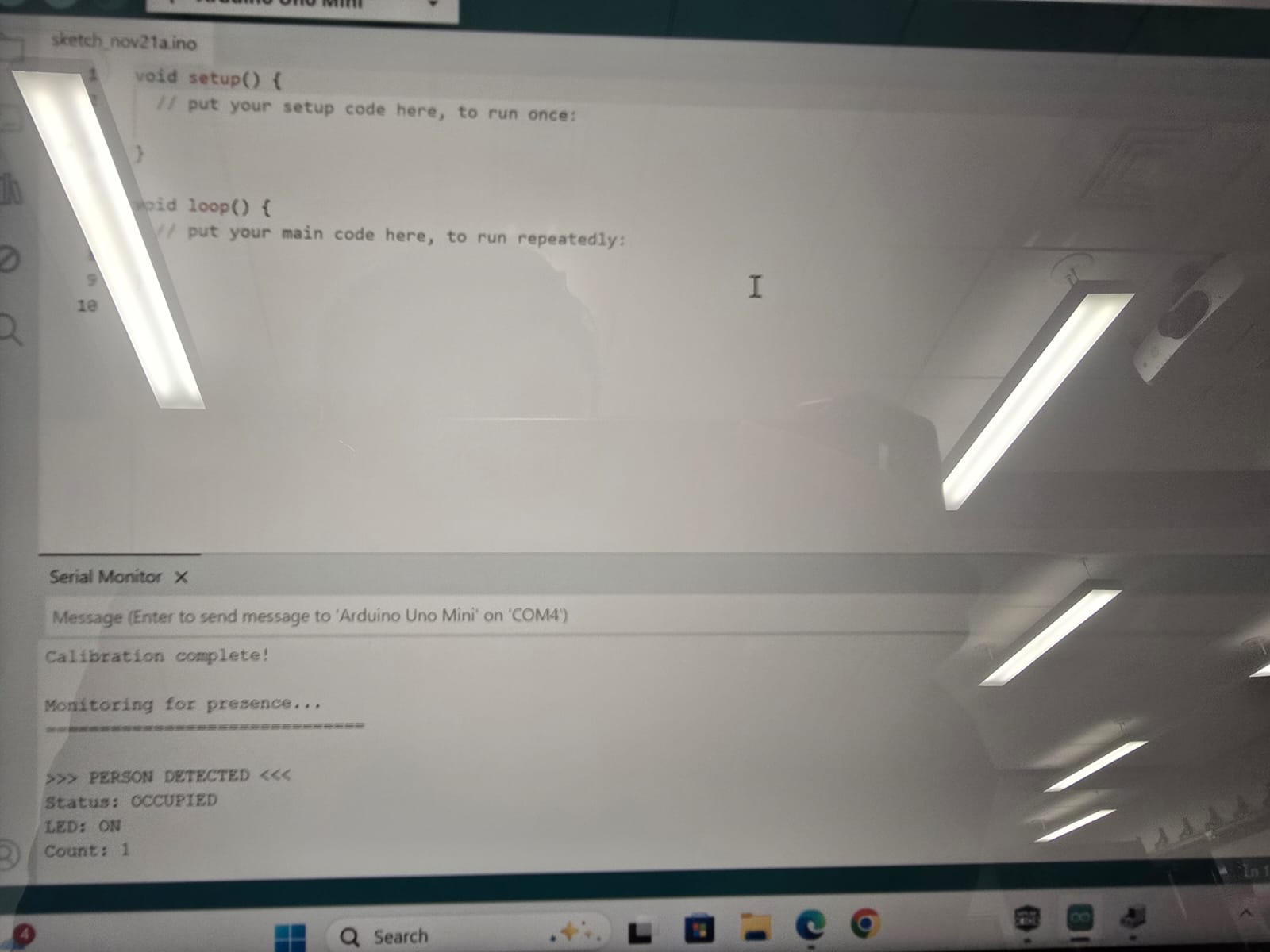
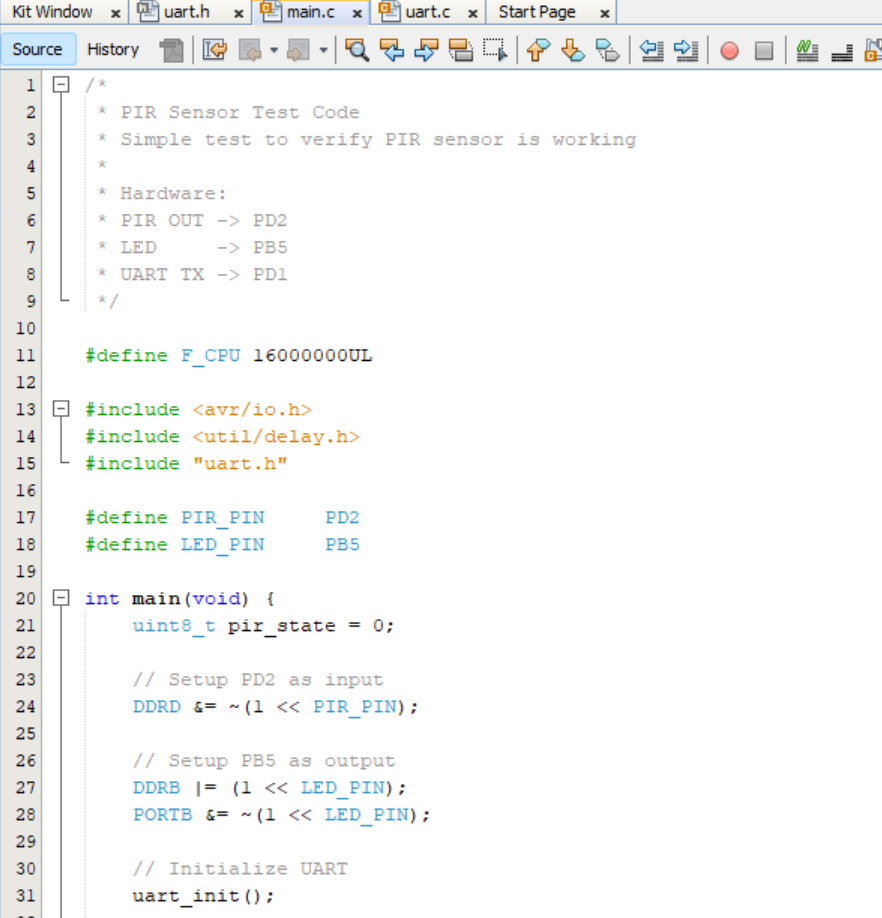
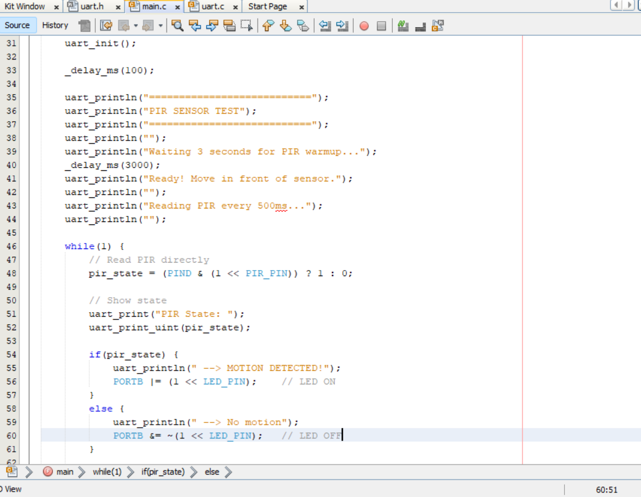
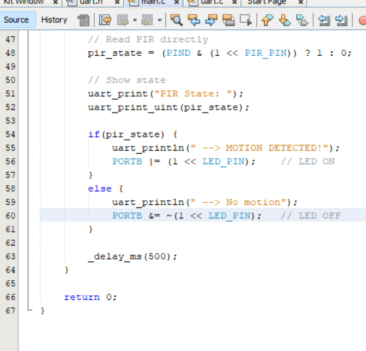
During this sprint, we successfully completed the integration of the PIR sensor with the ATmega328PB microcontroller. The PIR sensor was connected to PD2 for motion detection, and an LED indicator was connected to PB5 to provide visual feedback when a human presence is detected. The system communicates detection status through UART serial output at 9600 baud rate, allowing real-time monitoring via a serial terminal.Testing confirmed that the PIR sensor accurately detects human presence while filtering out non-human triggers. The LED turns ON when a person is detected and turns OFF when the person leaves, with corresponding status messages displayed on the serial terminal. The code was developed using MPLAB X IDE with XC8 compiler, utilizing bare metal programming without any external libraries for direct hardware control. The final build uses only 444 bytes (1%) of program storage and 9 bytes (0%) of dynamic memory, leaving ample room for future feature additions.
Overall, the project is progressing well and key subsystems are now functioning cohesively. The speaker and amplifier have been fully tested, resulting in improved audio clarity and stable performance. The firmware for both music playback and vibration motor control has been completed, and both modules are successfully integrated with the ToF sensors.
Here is screenshot of code that plays the music and checks the serial port continuously from ESP32.
Next week’s plan
Next week, our focus will be on system integration and MVP demonstration. We will combine all individual components including the PIR sensor module, posture detection system, and chair hardware into a unified working prototype. The integration phase will involve connecting all sensors to the ATmega328PB, merging the codebase to handle multiple sensor inputs simultaneously, and ensuring seamless communication between all components. Once integration is complete, we will conduct thorough testing to verify that all features work together as expected. The week will conclude with an MVP demo showcasing the complete posture monitoring system with human detection, demonstrating the core functionality to stakeholders and gathering feedback for future improvements.
MVP Demo
- Show a system block diagram & explain the hardware implementation.
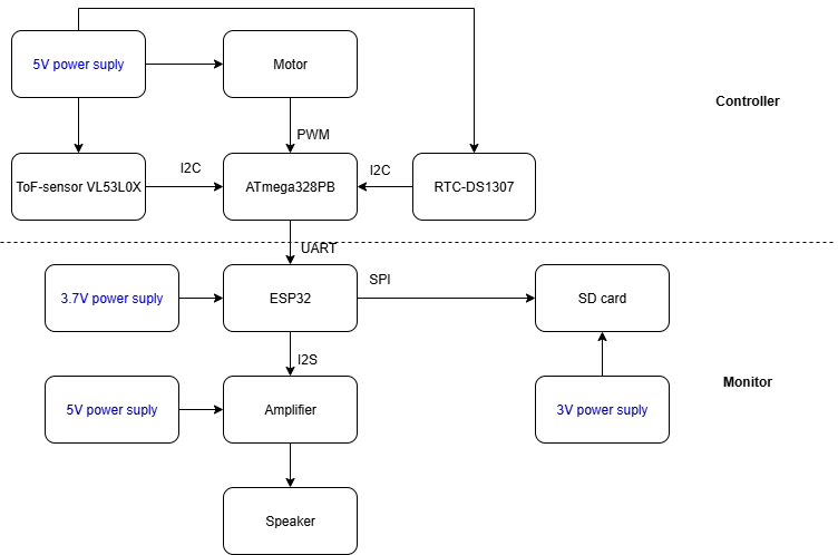
Two VL53L0X Time-of-Flight sensors are positioned to measure the distance between the user’s back and the chair at the different sections. These sensors communicate with the ATmega328PB via the I²C bus, which serves as the primary processing unit in the system. A DS1307 RTC module is also connected over I²C to provide real-time sitting duration tracking for long-term behavior monitoring.
The ATmega328PB continuously samples the two distance sensors and performs posture evaluation by calculating the difference between them. If the measured distance difference exceeds a preset threshold or if the accumulated sitting time exceeds a configured limit as indicated by the RTC, the microcontroller generates a PWM signal to drive a vibration motor. This provides immediate physical feedback to correct the user’s posture and to remind user to stand and take a break.
In addition to sensing and feedback, the ATmega328PB communicates with an ESP32 module via UART. The ESP32 handles voice output through its I²S audio pathway to an amplifier and speaker and can also log posture history to an SD card via SPI for future analysis and visualization.
- Explain your firmware implementation, including application logic and critical drivers you’ve written.
The firmware is implemented in a modular architecture, separating low level hardware access from application logic. The ATmega328PB functions as the sensing and MCU, while the ESP32 handles audio and extended feedback.
On the ATmega328PB side:
I²C / TWI driver: Implements the low-level I²C driver (Start, Write, Read, Stop, ACK/NACK). All VL53L0X sensors and the DS1307 RTC communicate through this module.
RTC timing module: Handles register-level I²C communication with rtc and provides APIs to read/write hours, minutes, and seconds for sitting-duration tracking.
VL53L0X ToF abstraction: Provides abstraction and distance-reading functions for VL53L0X Time-of-Flight sensors.
Port part: Configures UART for debugging output and for sending posture status messages to the ESP32.
Motor driver: Configures PWM using on-chip timers and drives the vibration motor for posture alerts.
PWM control, and application logic: Integrates all modules, performs continuous distance sampling, evaluates posture, monitors sitting duration, and triggers motor and speaker feedback.
On the ESP32 side:
Audio and feedback logic: Receives event messages from the ATmega328PB and plays stored audio files from the SD card through I²S, providing voice feedback alerts.
- Demo your device.
- Have you achieved some or all of your Software Requirements Specification (SRS)?
We have achieved the functions defined in the Software Requirements Specification. The system can continuously read distance data from Two VL53L0X ToF sensors, evaluate posture based on the difference between the sensors, track sitting duration using the RTC, and send feedback when the user sits incorrect or sits for too long. This confirms that the core detcetion-evaluation–feedback loop is fully functional at MVP level.
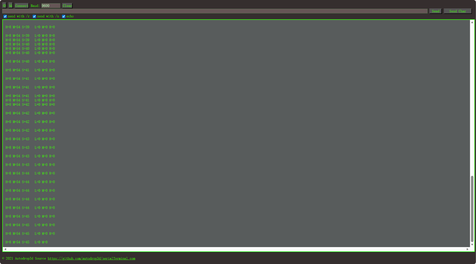
a. Show how you collected data and the outcomes.
We conducted continuous sampling tests using the Two sensors. The MCU periodically reads distances and calculates the difference between sensors to determine sitting posture and can control the mnotor to run. Below is the actual data output:
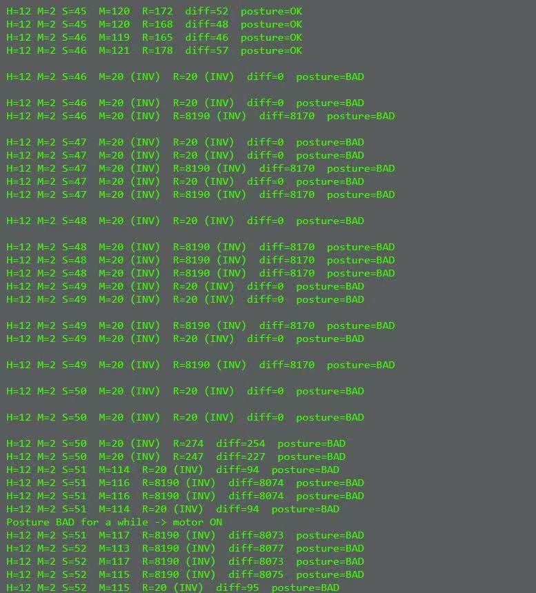
Meanwhile, posture status are transmitted to the ESP32 via UART. The ESP32 is responsible for generating voice feedback. When the MCU detects prolonged bad posture or timer expiration, the ESP32 triggers audio output through I²S to the amplifier and speaker, providing real-time auditory feedback to the user.
- Have you achieved some or all of your Hardware Requirements Specification (HRS)?
We validated the hardware functionality of our system through continuous real-user posture tests. The distance sensors remained stable during sampling, detecting distance between the user and the chair’s back. The DS1307 RTC provided real-time timestamps for duration tracking. Once the distance deviation exceeded the defined threshold and timer is end, the ATmega328PB triggered a PWM vibration motor as physical feedback, proving that sensing and response electronics behaved reliably.
In addition to monitor feedback, the ESP32 part was tested as the audio output module. Audio files were stored on an SD card and streamed through ESP32 via SPI, then decoded and played through the speaker. During testing, when prolonged bad posture was detected, the ESP32 successfully received the alert message from the MCU and played the warning audio stored in the SD card. This confirms that sensing → evaluation → monitor feedback → audio playback forms a fully functional multi-modal feedback loop.
a. Show how you collected data and the outcomes.
Video:MVPdemo.mp4
- Show off the remaining elements that will make your project whole: mechanical casework, supporting graphical user interface (GUI), web portal, etc.
Our important functional component is still pending: pressure sensor integration. The pressure sensor hardware has not yet been delivered, so seat occupancy detection is unavailable in the current version of the system. Once the hardware arrives, it will be incorporated as the first trigger stage of the workflow. The planned role of the pressure sensor is to detect whether a user is actually sitting. Only after seat-presence is confirmed, the posture measurement and timer logic will activate. This prevents false detection when the chair is empty.
Alongside upcoming sensor integration, we plan to develop a mechanical enclosure to mount all modules — ATmega328PB, ESP32, SD card, speaker, and motor — into one compact and ergonomic device. Additionally, we aim to introduce a visual interface for monitoring posture status, time tracking, and historical behavioral trends.
- What is the riskiest part remaining of your project?
The highest remaining risk in the system is the incomplete sensing hardware. Currently only two VL53L0X sensors are implemented for back posture measurement, while the design intends to include a third ToF sensor for head detection. Without this component, the system cannot fully observe upper-body posture, limiting its corrective capability. In addition, the pressure sensor has not yet been received, preventing accurate seat-presence verification, which risks false alerts when no user is sitting.
a. How do you plan to de-risk this?
First, integrate the third ToF sensor once we get, run calibration tests, compare its variance against back-sensor readings, and determine thresholds for whole detection.
Second, connect and integrate the pressure sensor upon arrival to enable seat-presence gating, ensuring posture evaluation only happens when a user is seated.
Third, conduct long-duration stress testing of I²C polling, motor cycles, SD and speaker audio playback and ESP32 streaming to verify reliability over hours of use.
- What questions or help do you need from the teaching team?
Thank You
Final Project Report
Don’t forget to make the GitHub pages public website! If you’ve never made a GitHub pages website before, you can follow this webpage (though, substitute your final project repository for the GitHub username one in the quickstart guide): https://docs.github.com/en/pages/quickstart
1. Video
Video:FinalProjectVideoo.mp4
2. Images
3. Results
The smart chair successfully integrates all major sensing, processing, and feedback components.
The ATmega328PB microcontroller reads data from the thin film pressure sensor, two VL53L0X ToF distance sensors, and the DS1307 RTC. These measurements are fused to classify posture and track sitting duration. When bad posture is detected and maintained for more than 5 seconds, the system triggers the vibration motor through a PWM driver stage and optionally sends posture status to an ESP32 via UART.
Overall, the final prototype works as planned. It can detect posture correctly, read all sensors reliably, adjust the vibration strength, and run safely with the power system. More detailed tests are shown in the next sections
3.1 Software Requirements Specification (SRS) Results
| ID | Description | Validation Outcome |
|---|---|---|
| SRS-01 | The system shall read analog data from one thin-film pressure sensors using the MCU’s ADC , updating seat-occupancy status and sitting-duration counters every 200ms . A user shall be considered “absent” if all sensor readings remain below a calibrated no-load threshold for more than 1s. | Verified. The thin-film pressure sensor readings were successfully captured via the ATmega ADC at 1 s intervals. Logged data show correct occupancy detection and accurate sitting-duration counting. The system reliably flagged “absent” when readings stayed below the calibrated threshold for >1 s. |
| SRS-02 | The system shall communicate with two ToF distance sensors over I²C and request distance data . | Verified. Both VL53L0X ToF sensors communicated over I²C without address conflicts (using XSHUT control). Distance measurements were successfully requested every ~0.2 s, with each transaction completing within 25–30 ms , satisfying the <50 ms requirement. |
| SRS-03 | The vibration motor shall be controlled via GPIO digital outputs with a reaction latency of 5s from the posture detection event. The duty cycle of the GPIO signal (PWM) shall be adjustable to provide variable haptic intensity. | Verified. The vibration motor was driven using PWM from the MCU. Duty-cycle adjustments resulted in noticeable variations in haptic intensity. Oscilloscope captures confirmed correct PWM output waveform. |
| SRS-04 | The speaker shall be controlled via GPIO digital outputs to emit an auditory alert with a reaction latency of <200ms. The output shall support configurable tone or voice prompts, with the volume level maintained within a safe, non-startling range. | Verified. The speaker was driven via ESP I²S. Audio alerts were successfully played, and the output amplitude stayed within safe and non-startling volume levels. Tests confirmed stable playback without distortion. |
| SRS-05 | The ESP shall transmit posture and sitting-time data via UART. | Verified. Posture classification results and sitting-time data were transmitted from ATmega to the ESP module over UART at the configured baud rate. Serial logs show consistent, error-free packet transfer. |
| SRS-06 | The system shall communicate with one RTC over I²C to get the time data. | Verified. The RTC (DS1307) communicated with the MCU via I²C. Time data (hours, minutes, seconds) were read correctly, and repeated reads showed stable and accurate timestamps. |
SRS-02, SRS-06: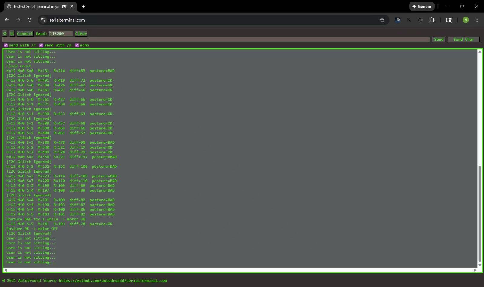
SRS-04, SRS-05: 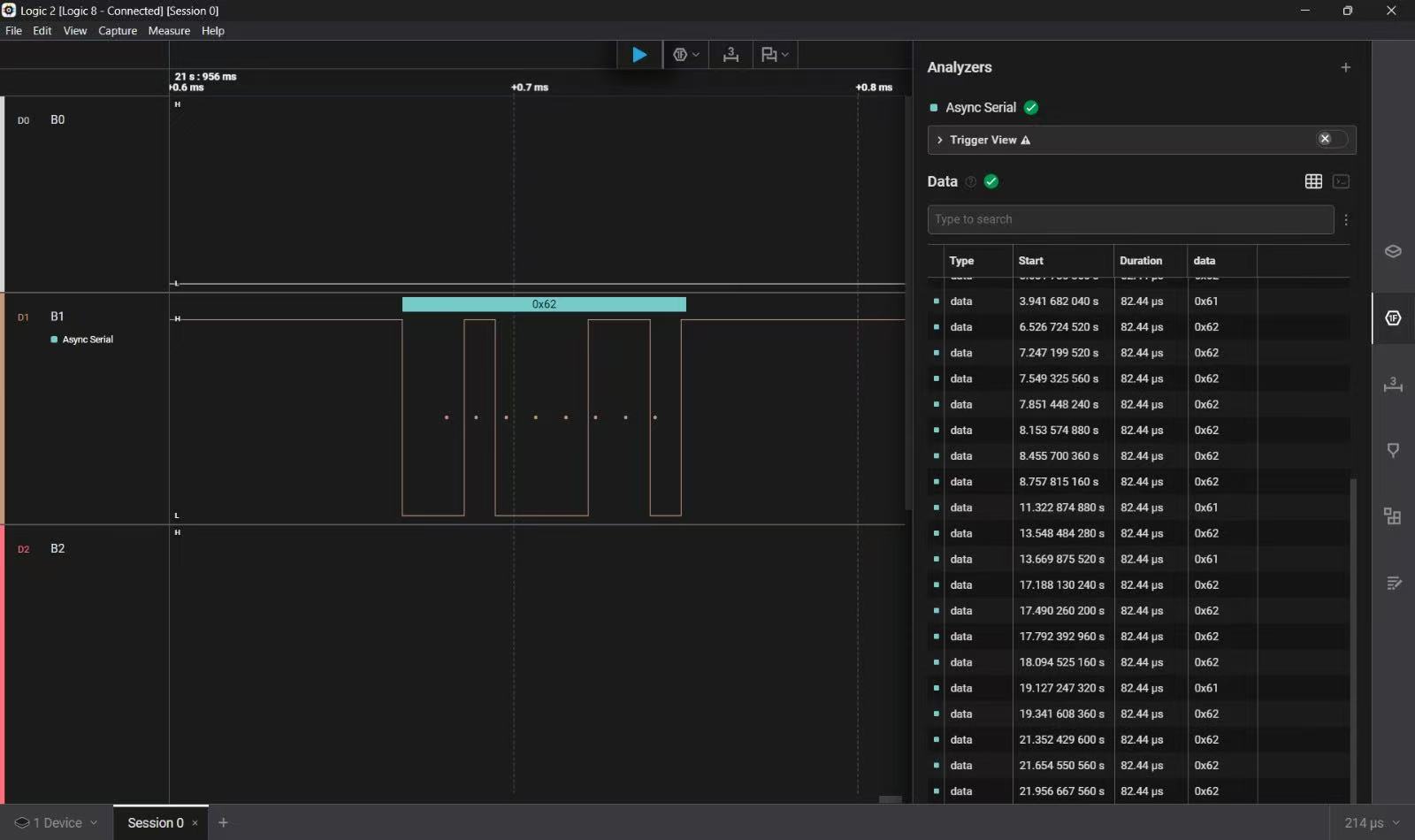
3.2 Hardware Requirements Specification (HRS) Results
| ID | Description | Validation Outcome |
|---|---|---|
| HRS-01 | The system shall measure seat pressure to detect occupancy. Initially, four pressure sensors were planned to be mounted on the chair legs, but these sensors were unavailable.Plan B: a single thin-film pressure sensor was used on the seat to reliably detect human presence. | Confirmed. The single thin-film pressure sensor successfully detected the presence or absence of a user. Video and test logs in the “validation” folder demonstrate occupancy detection. |
| HRS-02 | The system shall provide user feedback on posture status. Originally planned using an LCD display. | Requirement updated. LCD removed and replaced with a vibration motor. This improved the user experience and allowed the entire system to function as a single self-contained device without additional wiring or mounting for a screen. |
| HRS-03 | The system shall provide an alert for poor posture. Originally planned using a buzzer. | Requirement updated. The buzzer was replaced with a speaker, as the speaker can produce multiple tones or audio cues. It offers higher volume and greater flexibility compared to a single-tone buzzer. |
4. Conclusion
Reflect on your project. Some questions to address:
- What did you learn from it? I learned how to write firmware, integrate hardware and software, choose sensors and components using datasheets, combine individual modules into a complete system, and collaborate effectively within a group under a deadline.
- What went well? Our planning was strong, and we always had backup ideas to switch to when something didn’t go as expected.
- What accomplishments are you proud of? We were able to finish the project within the given timeline, and we managed our components and resources very efficiently.
- What did you learn/gain from this experience? I learned that having a Plan B is essential in hardware projects, and group work helps you learn new skills and perspectives.
- Did you have to change your approach? Yes, we had to use only two ToF sensors because the chair design we wanted was not available, and we replaced the four planned pressure sensors (for the chair legs) with a single thin-film pressure sensor because the original sensors did not arrive on time.
- What could have been done differently? We could have added Bluetooth-based alerts and developed a mobile app to send notifications directly to the user.
- Did you encounter obstacles that you didn’t anticipate? Yes, we did not expect the pressure sensors to be delayed or not arrive at all, which forced us to change our design.
- What could be a next step for this project? We can add head posture detection and build a mobile app to enhance user feedback and monitoring.
References
We split our firmware into two main parts: the ATmega328PB node (sensing + posture logic) and the ESP32 node (audio playback). Below we summarize the libraries and modules we used on each side.
ATmega328PB firmware
-
AVR standard headers
-
avr/io.h, avr/interrupt.h, util/delay.h
These are the core AVR-GCC headers. We use them for direct register access (GPIO, timers, TWI, USART), enabling/disabling interrupts, and implementing short blocking delays.
-
-
UART driver (UART.c/.h)
Our own driver around USART0/USART1. It provides:
- UART0_Init(), UART0_SendString() for debugging over serial to the PC.
- UART1_Init(), UART1_SendChar() to send single-character commands (‘a’ = start music, ‘b’ = stop music) to the ESP32 over UART.
-
TWI / I²C driver (twi.c/.h)
Custom blocking I²C driver using the ATmega TWI hardware (TWBR0, TWSR0, TWCR0, etc.).
We expose simple APIs like twi_init(), twi_start(), twi_write(), and twi_read_ack()/twi_read_nack(), which are then reused by the RTC and ToF sensor drivers.
-
RTC DS1307 driver (rtc_ds1307.c/.h)
Uses our TWI layer to:
- Configure the DS1307 real-time clock.
- Read and write time registers (in BCD).
- Provide a “get valid time” helper that filters out occasional I²C glitches and avoids bogus readings (like random 00:00:00).
-
VL53 time-of-flight sensor port (vl53_port.c/.h)
Abstraction around the VL53 sensors, including:
- XSHUT control to bring sensors in and out of reset.
- Changing the default I²C address 0x29 to 0x2A and 0x2B so both sensors can share the bus.
- Single-shot distance read in millimeters.
- A recovery routine (vl53_bring_to_known_state()) that reinitializes the sensors if we start seeing invalid or stuck readings.
-
Motor control driver (MotorControl.c/.h)
Configures a PWM channel to drive the vibration motor through a transistor stage.
We use a simple interface: MotorPWM_Init() and Motor_SetSpeedPercent() to turn the motor on/off or set intensity based on posture.
-
Pressure sensor driver (pressureSensor.c/.h)
Handles the pressure sensors embedded in the seat. It debounces the digital input(s) and exposes PressureSensor_IsUserPresent() so the main loop can easily check whether someone is sitting on the chair.
ESP32 firmware
On the ESP32 we handle SD-card audio playback and the I²S interface to the MAX98357A amplifier.
-
Arduino core (Arduino.h)
Provides the standard setup() / loop() structure as well as Serial and Serial1 for debugging and UART communication with the ATmega.
-
SPI and SD libraries (SPI.h, SD.h)
- SPI.h is used to configure the SPI bus pins (SPI.begin(SPI_SCK, SPI_MISO, SPI_MOSI)).
- SD.h is used to initialize the micro-SD card (SD.begin(SD_CS)) and to open the audio file (SD.open(“/music.wav”)) as a file stream.
-
ESP-IDF I²S driver (driver/i2s.h)
We use the low-level ESP32 I²S driver directly to send audio samples to the MAX98357A:
- i2s_driver_install(), i2s_set_pin(), and i2s_set_sample_rates() to configure I²S as 16-bit stereo, master-TX.
- i2s_write() to push PCM blocks from the WAV file to the DAC.
- i2s_zero_dma_buffer() to quickly silence the output when we stop playback.
-
Custom WAV parser and player
We wrote our own small WAV parser and playback loop:
- parseWavHeader() walks through the RIFF/WAVE chunks (“RIFF”, “WAVE”, “fmt “, “data”) to extract:
- Audio format (PCM),
- Number of channels,
- Sample rate,
- Bits per sample,
- Data offset and length.
- playWavFile(“/music.wav”):
- Reads chunks of raw PCM data from the SD card into a buffer.
- Streams the buffer to I²S using i2s_write().
- Monitors Serial1 for the ‘b’ command from the ATmega to stop playback early, close the file, and clear the DMA buffer.
- parseWavHeader() walks through the RIFF/WAVE chunks (“RIFF”, “WAVE”, “fmt “, “data”) to extract:
The ATmega328PB and ESP32 firmwares together form a simple two microcontroller system:
- ATmega side : posture detection, user-presence tracking, time-based sitting logic, vibration feedback control, and ‘a’/’b’ commands over UART.
- ESP32 side : file I/O from SD and real-time audio streaming over I²S to the MAX98357A amplifier, controlled via the UART commands received from the ATmega.
COVER:
