final-project-f25-underdogs.github.io
Final Project Report
1. Video
Link to video demo: https://drive.google.com/file/d/1ZmYd9pcVVfsIZrL_sggFRo0MlVHi0CtK/view?usp=sharing
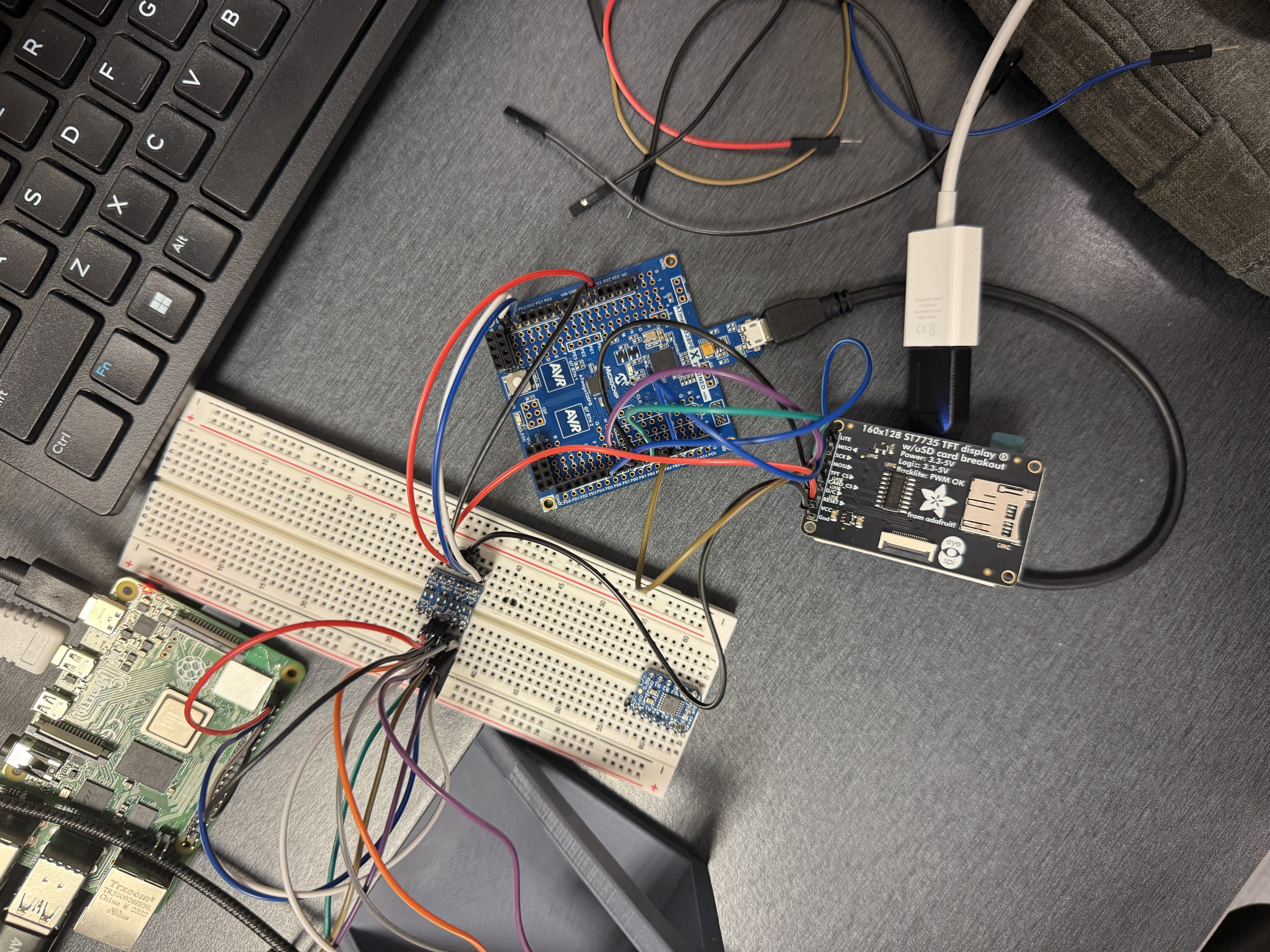
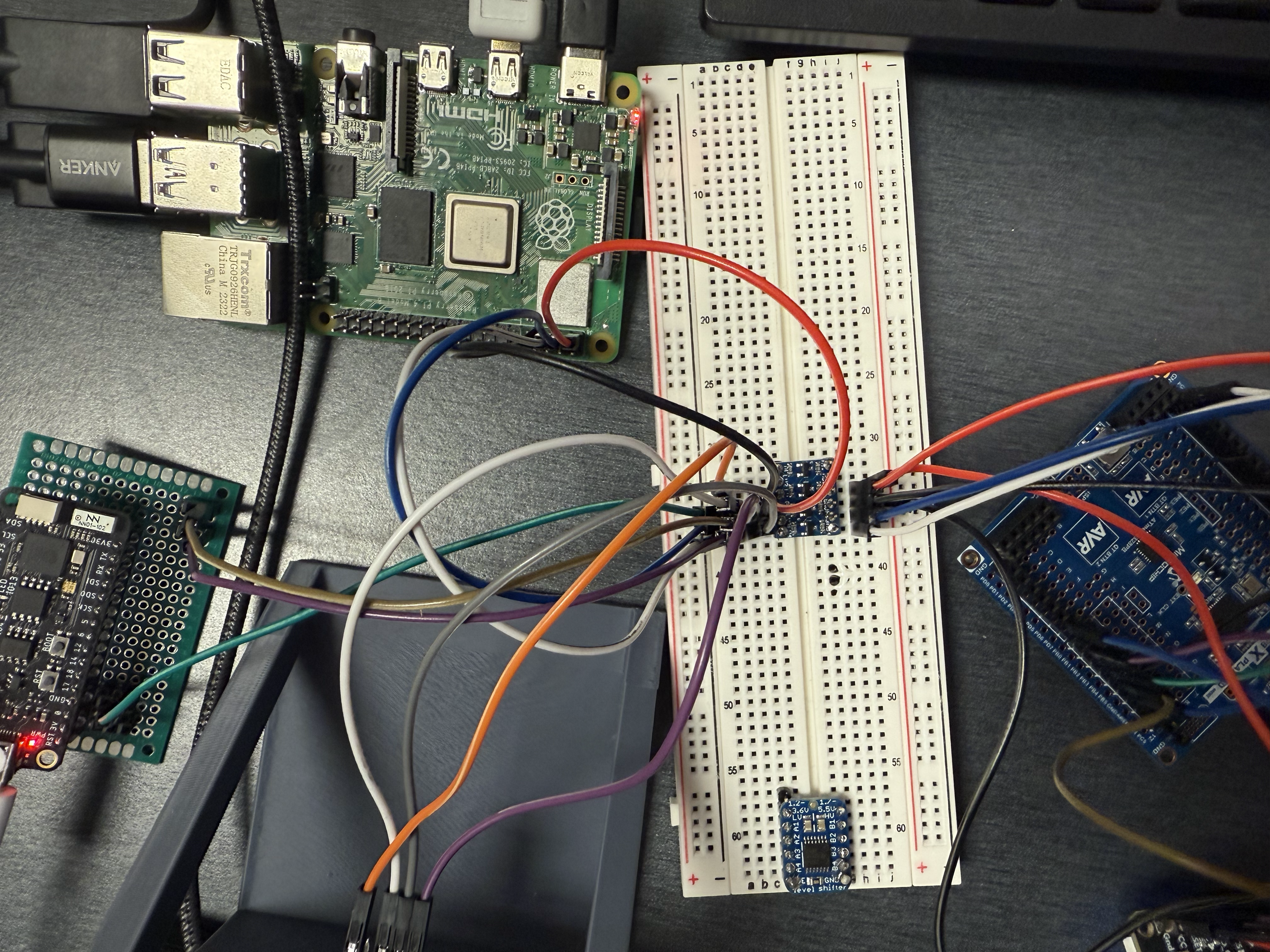
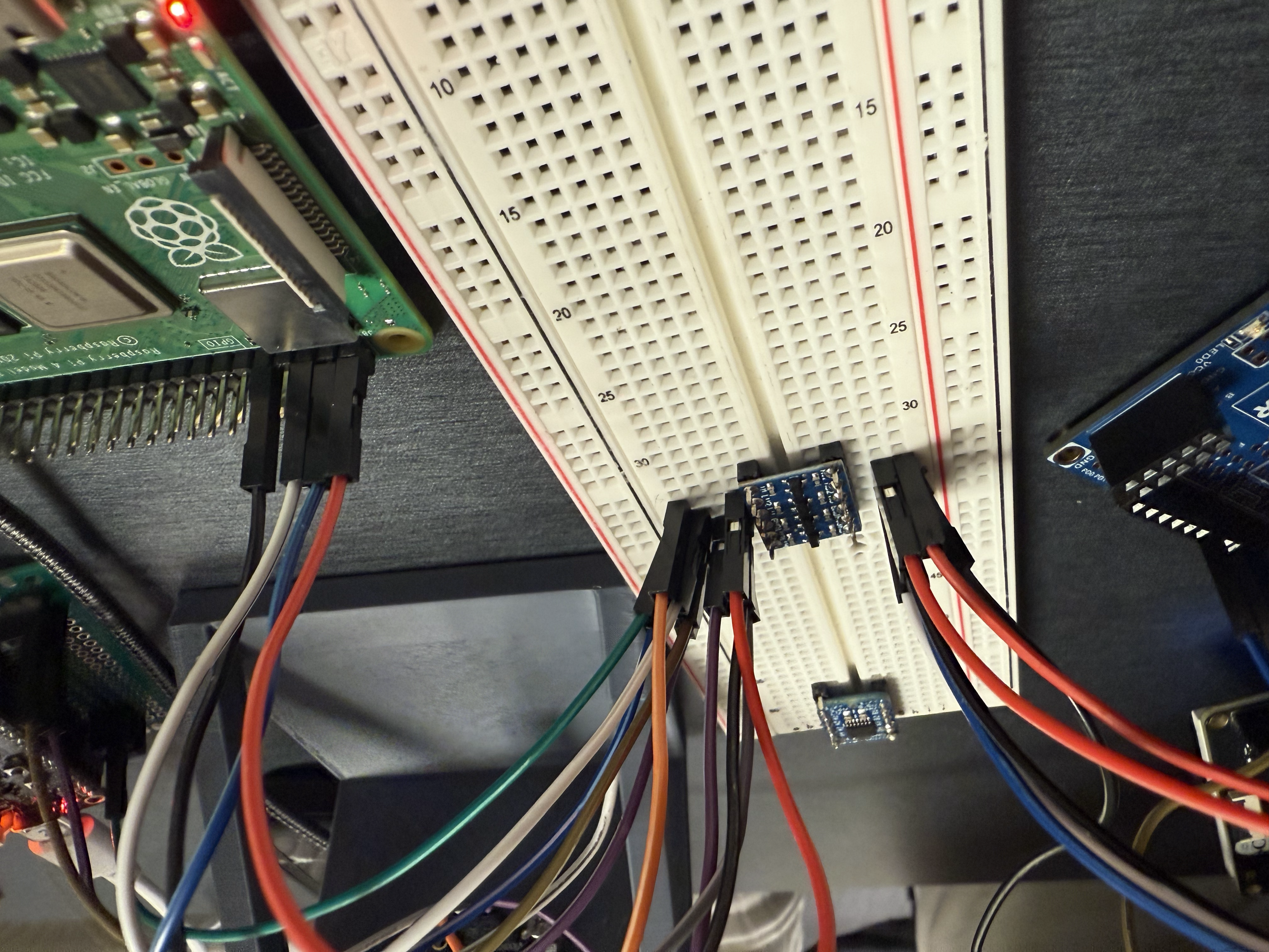
2. Images


3. Results
Our final solution consisted of five key components. We will enumerate each, and provide their role in the project:
- ESP Network: The ESP network was the primary form of data collection and transmission, and comprises the majority of the physical, interactive componentry of the project. The network is composed of two sensors, set into soldered header pins alongside ESP32S2-chipped FeatherS2 boards, as well as a primary controller FeatherS2 board wired into an I2C bus to communicate with the ATMega328PB and Raspberry Pi. Each of the peripheral sensors were independently powered by LiPo batteries, giving them portability, mobility, and enabling remote deployment. By running simple I2C/ADC data processing functions in conjunction with the ESP-NOW wireless communication protocol, the sensors were able to send data packages to the central controller, providing quantifiable metrics which monitored crowd engagement.
- RTRLOS backend: The RTRLOS backend is essentially the glue that holds the user-interactions together with the pretrained neural network and the sensor readings. The RTRLOS backend reads from the Raspberry Pi the data from our thermal camera and ESP network, and sends them to the frontend. Correspondingly, it takes in user input and orchestrates the functionality of our application, including collecting the sensor readings for a specific song and learning whether it was a good or bad choice via reinforcement learning.
- Frontend: The frontend was developed with Lovable. It provides the means for interacting with the backend, including observing sensor data, choosing songs to play, and observing the reinforcement learning loss based on the songs chosen and the corresponding sensor readings.
- Raspberry Pi Backend: The Raspberri Pi backend serves as the master for the I2C bus and transmits the data from the ESP Network and thermal camera to the frontend. The Raspberry Pi is the main orchestrator behind the communication in our sensor network; it gets data from the ESP and the Thermal Camera via I2C, and sends the data to the ATMega via I2C. It sends the data to the backend over WiFi. Note that in our implementation, it is important that the Pi is on the same WiFi network as the backend. In our case, we connected them to the same hotspot connection on an iPhone.
- ATMega LCD connection: The ATMega acts as a slave receiver. It receives data from the Pi via I2C, and prints it out to the LCD. The I2C driver was developed in-house, and the LCD driver was from lab 4. While the LCD is printing out, we do not take any input from the pi. Printing takes roughly five seconds.
Diagram of our Final Implementation:

You will notice that I2C is the main form of communication between our controllers, and the Pi acts as the brains of the sensor backend, coordinating communication between the main ESP, the ATMega, the thermal camera, and the RTRLOS backend. The Pi gets data from the main ESP and the thermal camera via I2C, and sends data to the ATMega via I2C. It sends data via WiFi to RTRLOS.
3.1 Software Requirements Specification (SRS) Results
| ID | Description | Validation Outcome |
|---|---|---|
| SRS-01 | DJ Interfacing: A corresponding software will be provided that allows the DJ to input the actual song chosen and the algorithm back-propagate | This is confirmed by the user-interface created and the corresponding video shows proof of this work. |
| SRS-02 | Sampling & Scheduling: Data is sent from the ATMega to the Mac over UART at 9600 bps with the schema: t_ms, of_dx, of_dy, tof_mm, thermal_avgC |
This was not done; instead, we favored a WiFi approach, which in fact worked better than this approach. The ATMega receives data via the Pi and sends it to the LCD now. |
| SRS-03 | Reinforcement Learning: The Mac software will provide the RL module with a state vector from our sensor data and played songs every 100 ms, and compute a reward. | Confirmed - The Mac is able to successfully receive data at ~100ms (as confirmed in the user interface), and reinforcement learning is successfully done, as confirmed in the user interface loss section as well. |
| SRS-04 | Sensor Peripheral Network: Sensors will communicate wirelessly within a multi-peripheral, single-controller structure and provide instantaneous, independent updates to chosen metrics. | Confirmed - multiple-peripheral, single-controller architecture was deployed and fully operational. Each sensor was tested and can send data independent of the other. All desired metrics measured. |
| SRS-05 | Sensor Frequency/Refresh: Sensor reading frequency and information transmission rate will exceed use case by Raspberry Pi-based RLRTOS. | Confirmed - use case of RPi-based RLRTOS confirmed to be 2Hz, each sensor peripheral code contains intentional delays to slow data transmission rate to between 1-2Hz (capability exceeds necessary use case).) |
| SRS-06 | ESP32ATMega/RPi Communication/Integration/Complexity Requirement: Each of the three microcontrollers will communicate seamlessly over various protocols and retain their unique functionalities in the project. | Confirmed - ATMega, ESP, and RPi all communicated with a common I2C bus. ATMega ran LCD code, controller ESP collected and packaged peripheral sensor data, RPi received and processed thermal camera data and ESP data. All roles and abstractions were upheld. |
| SRS-7 | Peripheral Code Legibility/Modularity: Code for peripheral sensors will be well-documented, with use of external libraries to be well-understood. Code will be legible, expandable, and well-commented. | Confirmed - use of external libraries minimal, only where necessary, with clear demonstration of understanding. All helper functions and code logic well-documented. As many code functionalities abstracted to helper functions as would make sense to maximize portability, legibility, and flow of code. |
3.2 Hardware Requirements Specification (HRS) Results
| ID | Description | Validation Outcome |
|---|---|---|
| HRS-01 | Sensor Construction: Sensors mounted so that Thermal camera has full forward FOV, and other sensors are unobstructed in their measuring capacity. | Confirmed - Custom standup created for thermal camera to be protected from crowd while having a front-facing view. Peripheral sensor casework was customized to allow for full sensor functionality while offering circuit protection. |
| HRS-02 | Sensor Portability, Fit, and Finish: Sensors will be implemented in such a way that they can be deployed around a dance floor, club, or other venue without interrupting event flow. They will be protected in casing, accessible, and powered remotely. | Confirmed - Sensors and peripheral FeatherS2 boards were placed into soldered and wired perfboards for robustness. Each sensor pack was equipped with a LiPo for form factor and sustained remote use. Sensor-specific casing was designed to protect circuitry while not hampering sensor function, with 3D printing, metal hardware, and isolating standoffs integrated into casework. |
| HRS-03 | Sensor Performance: Sensors will be able to run >2 hours consecutively remotely from the control station. Sensors will be able to communicate eover 100 feet of distance wirelessly. Sensors will be well-calibrated on baseline metrics. | Partial Confirmation - Sensors were calculated (with testing to confirm) to run between 45 minutes and 1 hour continuously. This was well-known based on the capacity of the LiPos chosen. This was not a desired outcome, but necessary with the materials available within the Detkin Lab based on part delays. The sensors were measured to communicate wirelessly in excess of 100 feet, and calibration was implemented within software to offset sensors for an intense club/party environment - see microphone code for specifics.) |
| HRS-04 | Sensor Robustness: Sensors will provide at least three additional data streams by which crowd engagement can be judged. These data streams will be able to be directly correlated with crowd engagement. | Confirmed - Sensors provide Raspberry Pi with thermal image deltas, audio variation, and various environmental parameters (temp, humidity, etc.). Each of these measurements is positively correlated with positive crowd engagement, measuring physical activity/exertion, volume, and physical response to the music.) |
| HRS-05 | External Interrupts: The Optical Flow MOTION line will be connected to PD2 (INT0) and configured for falling-edge trigger. | This was not done; our design changed so much, and was vague to such an extent that it rendered this hardware requirement obselete |
| HRS-06 | Resistor Divider: A resistor divider will be used between the LDO and the optical flow sensor to maintain bits sent while decreasing voltage. | This was not done, again, for the same reason; our design changed so much, and was vague to such an extent that it rendered this hardware requirement obselete |
| HRS-07 | RUART/USB Output: The Mac output device will be connected via the Xplained Mini’s on-board USB-UART bridge; no external TX/RX wiring shall be required. | This was not used in favor of the Pi WiFi. |
4. Conclusion
Overall, our approach changed drastically from this project’s onset. Originally, we did not know enough about the problems we were going to face. One of the biggest problems we faces was coding in bare-metal on the ESP32s. The level of abstraction that ESP32S2 boards are intended for means that coding in baremetal C is extremely difficult, with Espressif not providing sufficient register documentation to even implement simple register-manipulation functions, like ADC conversion. This led to concerns over complexity factor, given that the ESP code would mostly rely on C++-level code and external libraries to work properly. To solve this, we decided to augment our project and create an I2C driver on the ATMega to facilitate communication between the sensors and the LCD and satisfy the bare-metal requirement.
One major obstacle we faced was an I2C driver that was not working the night before the final project was due. After some time troubleshooting this bug, we found the problem was with the level-shifter. Essentially, the buffer-type level-shifter was not meant for I2C communication, and therefore our Pi was unable to communicate with our ATMega. Finding the problem was the difficult part, but solving the problem itself was easy: We simply replaced the level-shifter with a different one, and the Pi was able to detect it easily.
On that note, one of the primary learning points of this project was almost certainly the need to exhaustively test communication protocols. We ran into many communication-related issues over the course of project implementation - crossing data streams, data type conversion, even real-world examples of the priority interruptions/interrupt-based programming that we learned about in class. The main takeaway is to simplify datastreams as much as makes reasonable sense - having more data going between sensors and microcontrollers than is strictly necessary can contribute heavily to a confusing and buggy implementation.
Each of the two individual project halves were developed in tandem and function exactly as intended individually. This is a pride point for each of the two engineers on this project, as the work was mostly halved. While this development style ultimately made full integration the most difficult part of project completion, it also allowed us to each master a distinct and necessary part of the project - this was great for learning, development, and ownership. In that vein, I think the ability to put together a robust, user-facing product that hits almost all specifications and operates as intended in all cases is a great pride point considering we were each doing 50% more work than expected for a final project. Integration beyond the embedded level was also a major plus of this project - integrating a full web app, higher-level wireless communication protocols, and some level of packaging robustness made this feel much more like a complete product than a simple prototype electronics project.
Without the bounds of ESE5190, we would almost certainly integrate this project without any baremetal C. The point of the course was to learn at the register-shifting level, and as such the need to implement in baremetal to satisfy a complexity factor was understandable. However, the integration of the ATMega328PB felt more like a bone-toss than anything that was actually adding value to the project. The LCD could be implemented at a higher level of abstraction to make the project more simpler and involve less moving parts.
There are a many directions we could take this project in the future. One possible direction is engineering a robust playback algorithm that includes overlapping stems of songs (i.e., acapellas and instrumentals) and mixing songs together. We could also collect more data and engineer a more robust learning algorithm. The current algorithm is very “quick and dirty,” and creating a better algorithm with more rich data is sure to improve performance and user experience. On the hardware side, a more varied/complete sensor stack with beefed-up LiPos, further-iterated casework, and more calibration would be beneficial to bringing more robustness to this product. Switching the thermal camera from I2C with the RPi to a remote peripheral module would be a nice touch and allow the camera to be deployed away from the RPi. Adding LiPo voltage indicator lights, switches, and more robust USB-C ports would be additional user-facing integrations for the sensors modules.
References
Fill in your references here as you work on your final project. Describe any libraries used here.
- LCD Library from Lab 4 Pong
- I2Cbus library for Raspberry Pi
- npm package manager for frontend (packages used for frontend in
packages.json) - Python libraries to facilitate RTRLOS functionality. Listing them all is beyond the scope / self-explanatory from the .py files, but some notable mentions include
pytorch,asyncio,librosa, andfastAPI - Adafruit BME680 Library - a necessity due to the backend code run by BME680s being protected IP by Bosch. Consumers are not allowed free access to the code, and so library abstractions must be used. Implements read functionality from the BME680.
- Arduino Wire Library - a necessity due to register-shifting functionality to implement I2C in baremetal abstracted by Espressif, the maker of the ESP32S2 chip. Implements I2C between the ESP32S2 and other peripherals.
- analogRead Function - a necessity, once again, due to register-shifting documentation being insufficient to implement a baremetal ADC conversion function on the ESP32S2 chip. Reads input voltage from an analog pin.
- ESP-NOW Library - Allows for the implementation of an ESP chip-specific wireless communication protocol between ESP-powered boards.