final-project-website-submission-f25-t05-f25-safeguard_secure

ESE 5190 Final Project: SafeGuard Secure
Team Number: 5
Team Name: SafeGuard Secure
| Team Member Name | Email Address |
|---|---|
| Chengzhi Huan | huancz@seas.upenn.edu |
| Fabian Sander | fsanderh@seas.upenn.edu |
| Andy Yu | yu86@seas.upenn.edu |
GitHub Repository URL: https://github.com/upenn-embedded/final-project-f25-f25-final_project-safeguard_secure.git
GitHub Pages Website URL: https://upenn-embedded.github.io/final-project-website-submission-f25-t05-f25-safeguard_secure/
Final Project Proposal
1. Abstract
This project implements an intelligent dual-verification access control system that integrates embedded processing, machine learning, and wireless communication to create a secure and automated door mechanism. The system authenticates users through a gesture recognition stage followed by a secondary numeric verification, combining vision-based identification with user interaction for improved reliability. Real-time monitoring and notifications are provided through a wireless interface that reports system activity and access events.
The goal of the project is to design an integrated embedded platform that combines perception, decision-making, and actuation within a single system. This work emphasizes the challenges of merging sensing, control, and communication subsystems into a reliable, responsive, and user-aware device.
2. Motivation
Traditional access control systems in schools often rely on physical ID cards to unlock doors. However, this presents several challenges: students may forget or lose their cards, and PIN-based systems are vulnerable to unauthorized access through password sharing. These limitations highlight the need for a more intelligent, secure, and user-friendly solution.
This project aims to develop a smart door lock system that leverages machine learning to recognize user gestures as one of the criteria for access. In addition to that, entering the correct PIN code is also required to gain access.
By integrating a camera, presence sensor, door sensor, number pad and LED strip, the system not only automates the locking mechanism but also provides real-time feedback and situational awareness. Administrators can monitor the door status remotely and make updates through their smart devices.
What makes this project particularly interesting is its fusion of AI-driven decision-making with embedded hardware for enhanced security and convenience. The intended purpose is to create a robust, responsive, and secure door access system that improves user experience, strengthens safety, and enables remote monitoring and control.
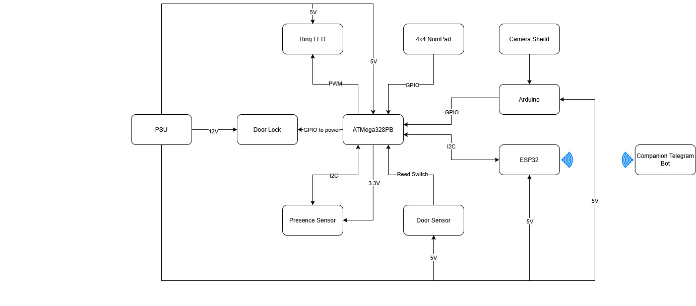
3. System Block Diagram
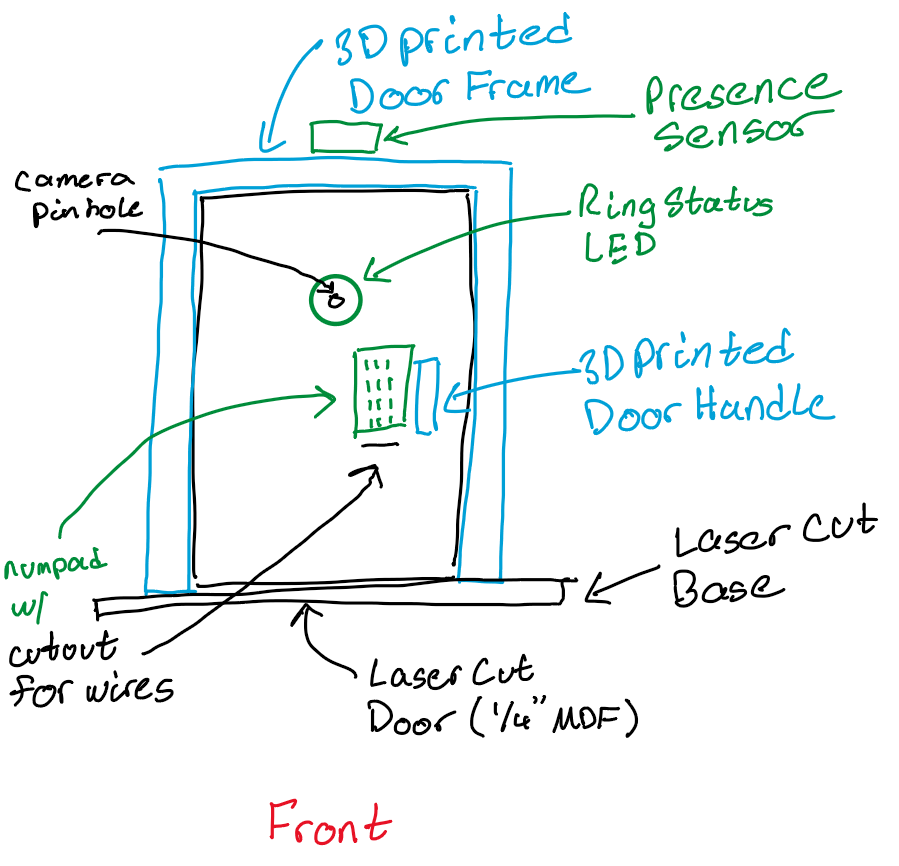
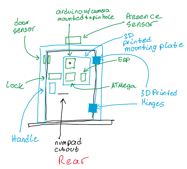
4. Design Sketches
What will your project look like? Do you have any critical design features? Will you need any special manufacturing techniques to achieve your vision, like power tools, laser cutting, or 3D printing? Submit drawings for this section.
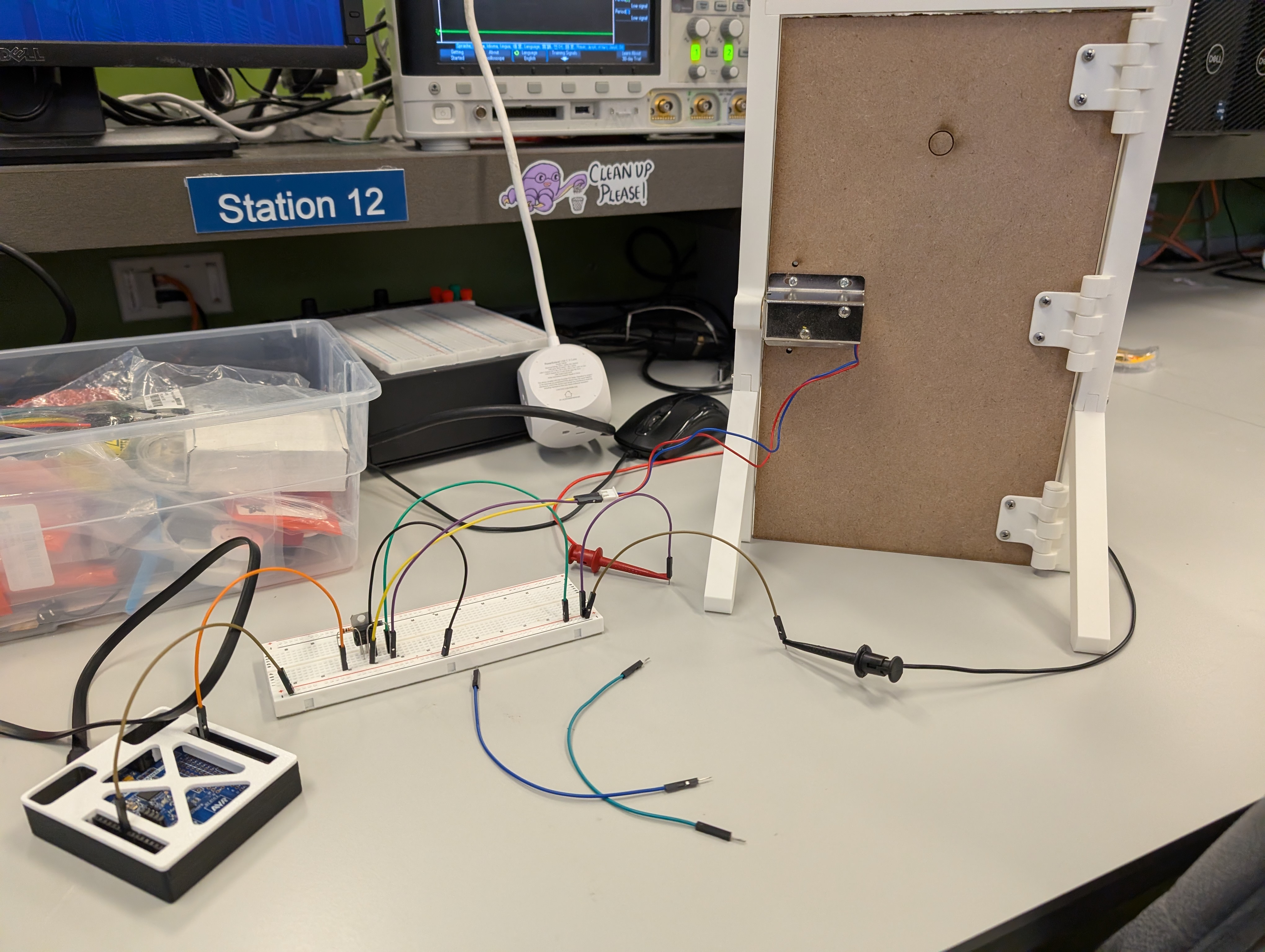
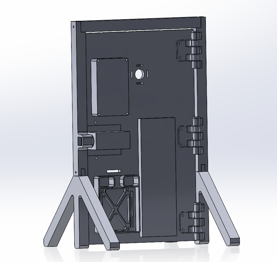
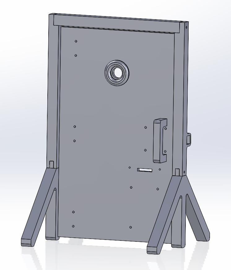
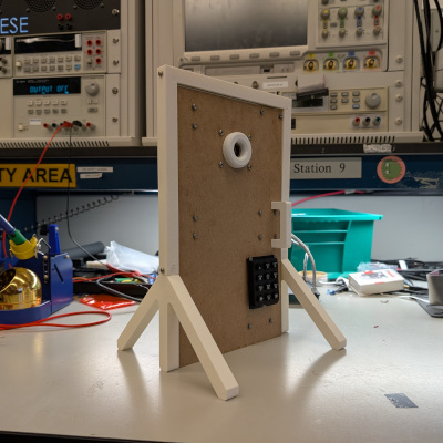
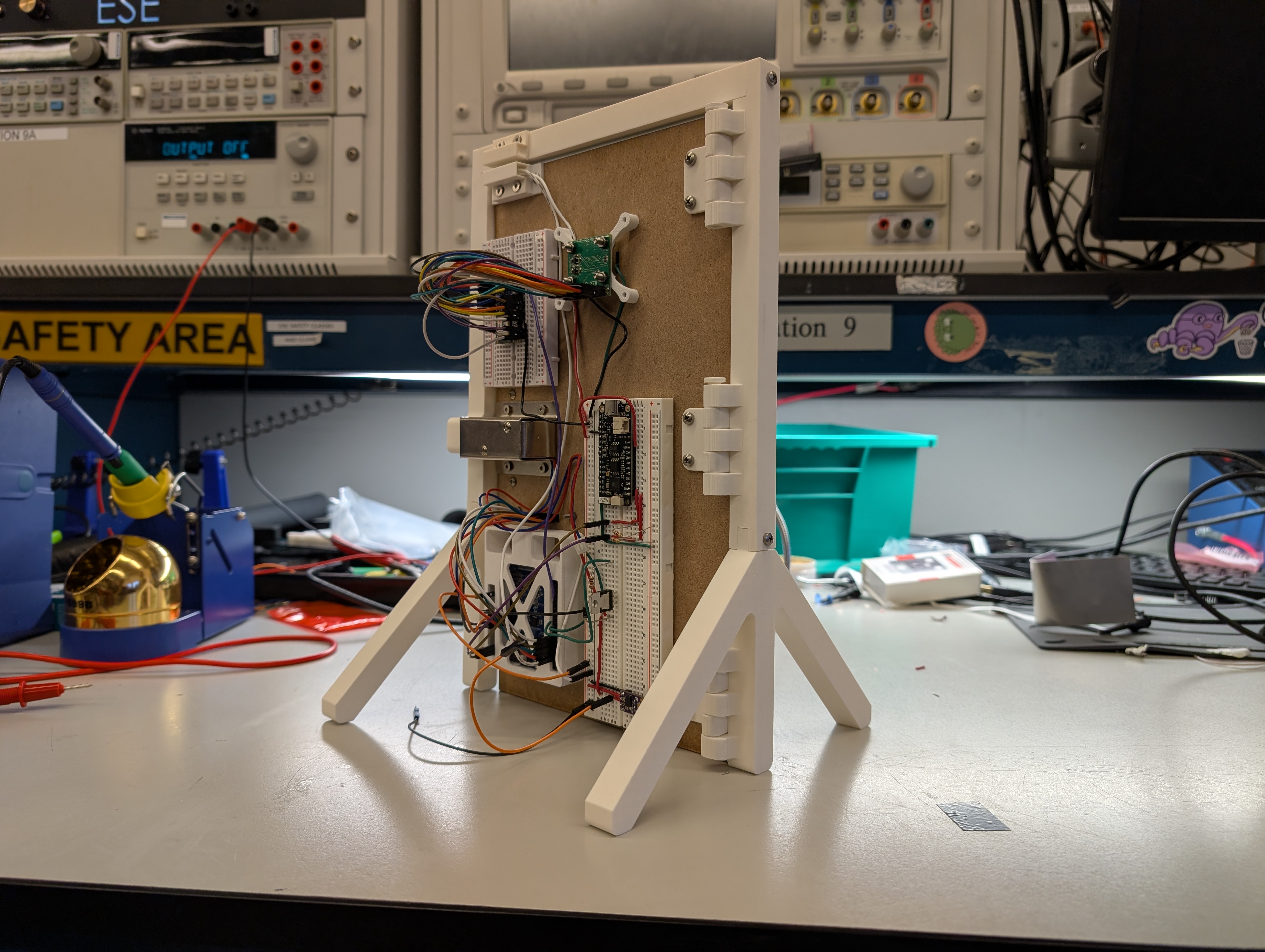
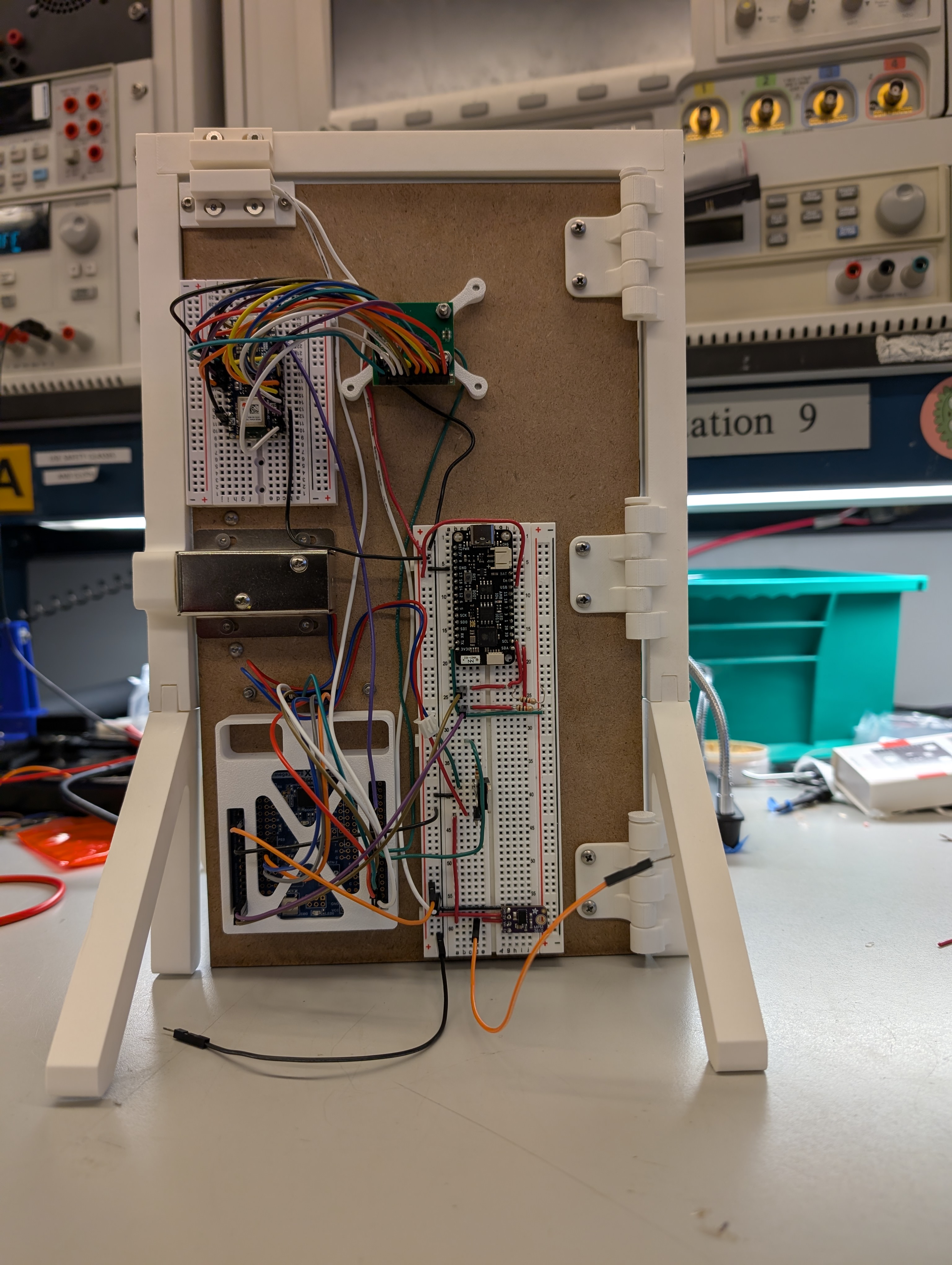
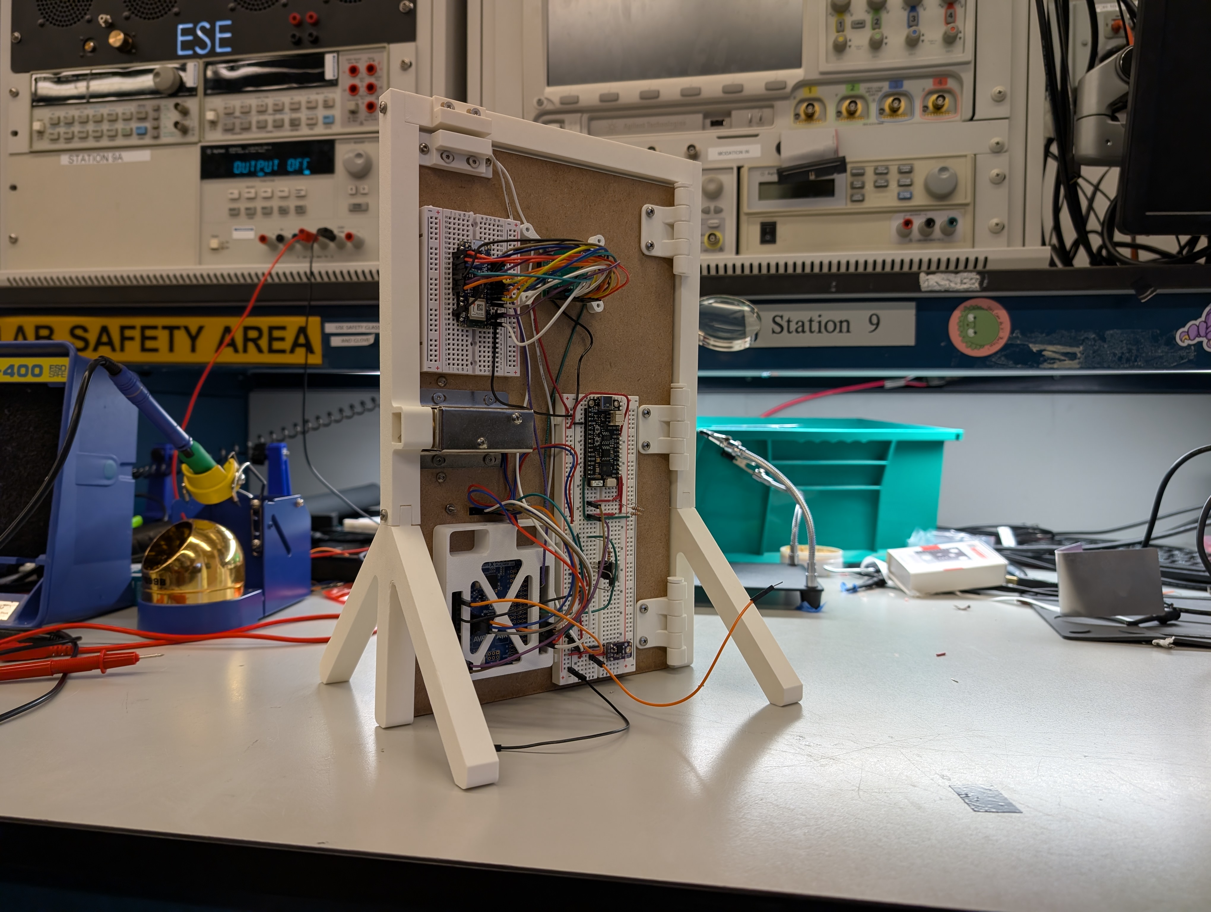
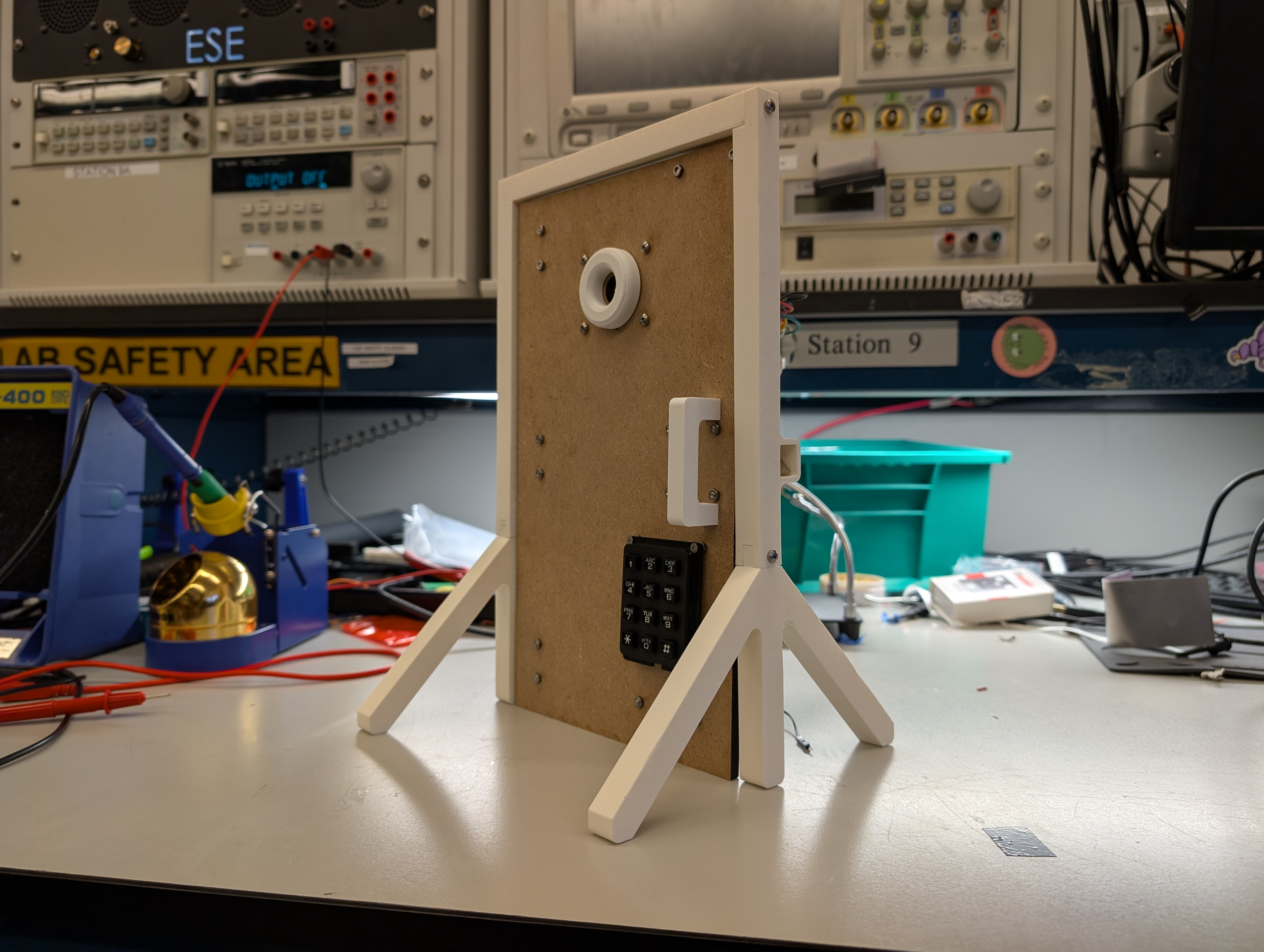
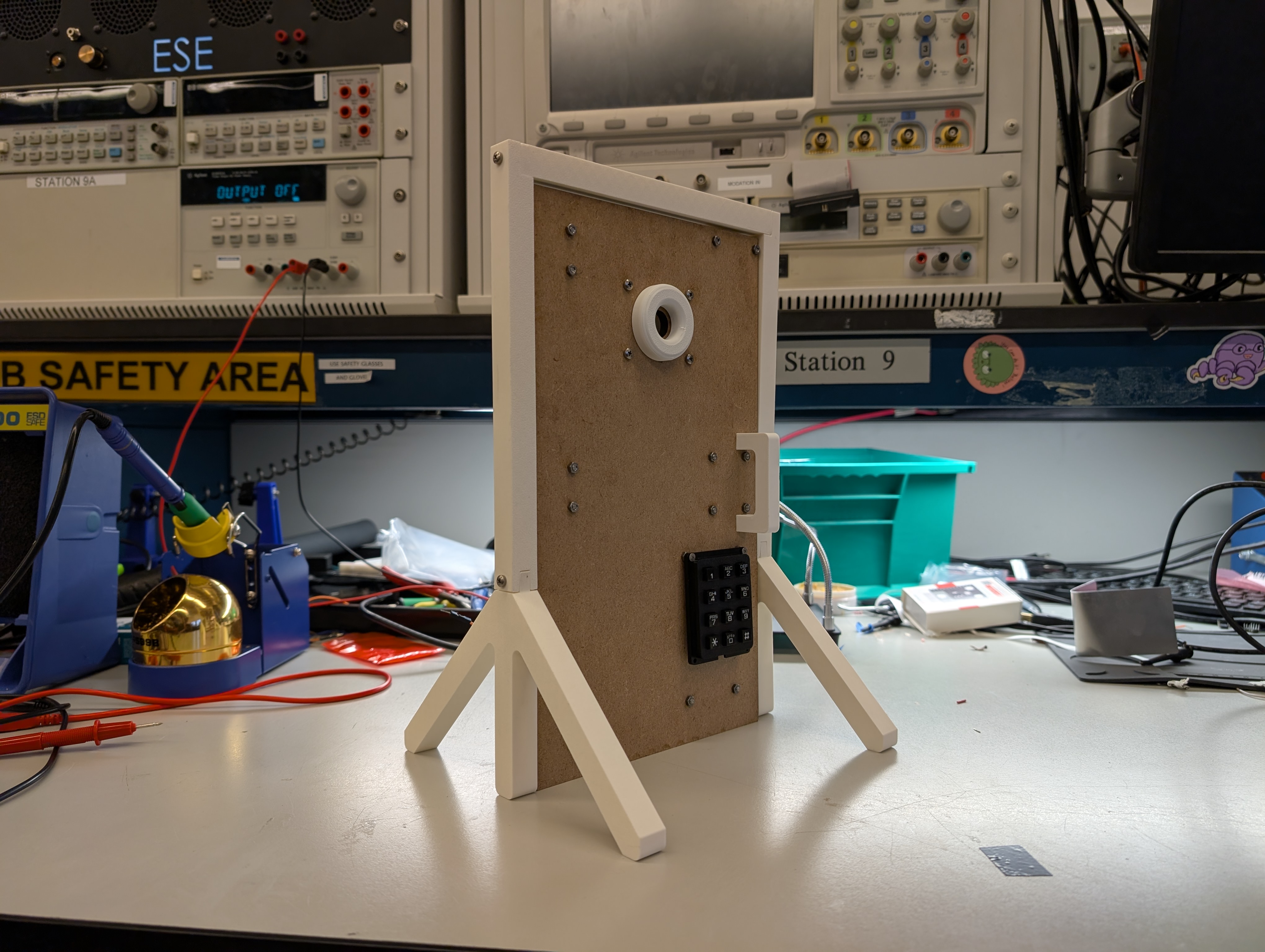
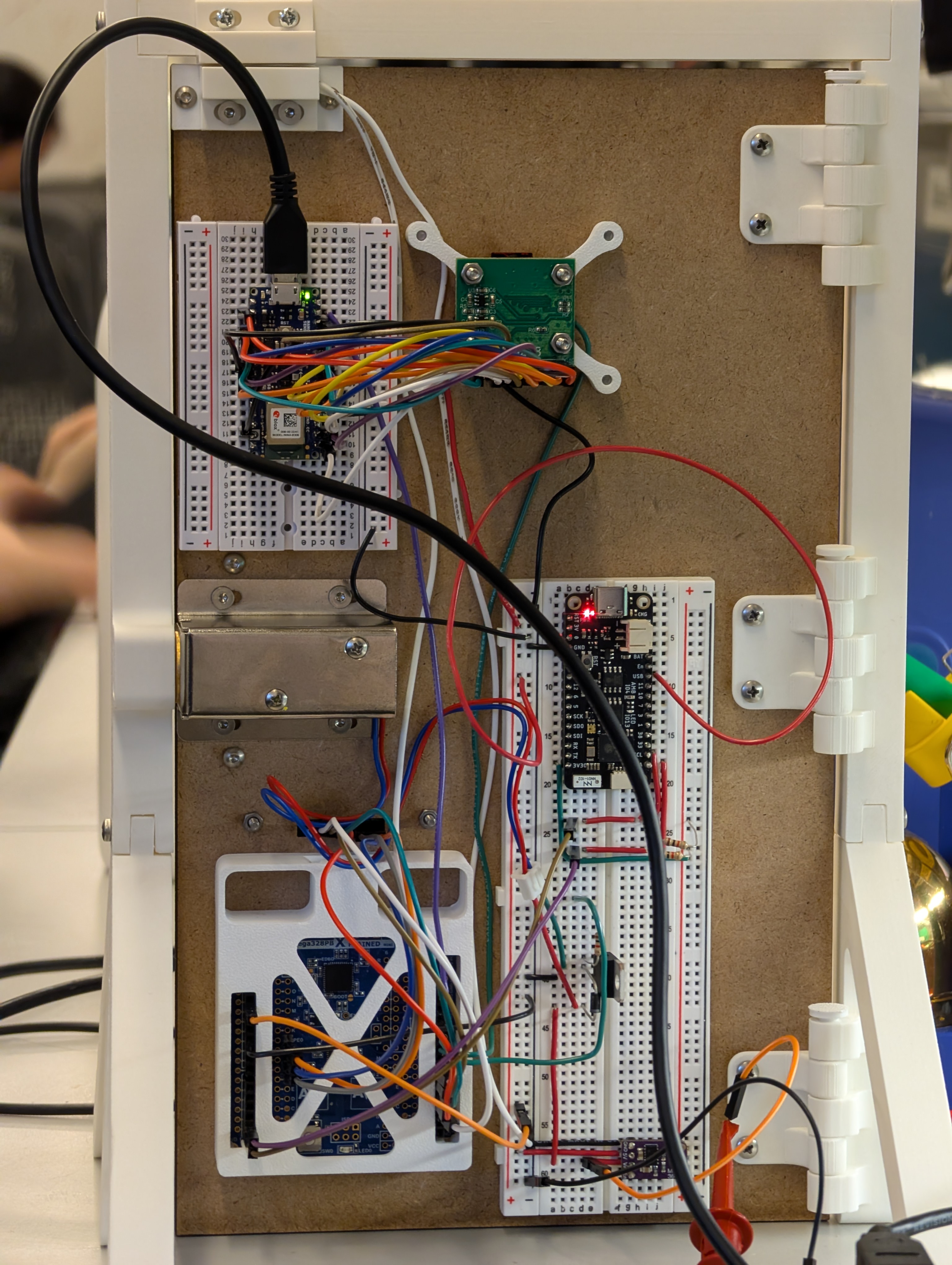
The project will be mounted to a mock up miniature door. The door frame will be 3d printed with a cutout for the deadbolt and mounting points for either a 3d printed or laser cut base. The door frame will also have a mounting point for the presence sensor at the top. The door itself will be laser cut with cutouts for the camera and wire pass through for the numpad. There will also be cutouts for mounting hardware such as a 3d printed door handle. A 3d printed mounting plate with cutout for the camera will be used to mount the ATmega, ESP32, and Arduino with camera to the rear of the door. The plate will also hold a breadboard for ease of wiring along with where the power will be supplied to. The door sensor and lock will also be mounted to the back of the door. All mounting hardware will either use wood screws or pilot holes will be made to to try and mitigate the use of power tools. VHB tape will be used for anything without mounting holes or as a back up. The door itself will be mounted to the door frame with 3D printed hinges.
5. Software Requirements Specification (SRS)
5.1 Definitions, Abbreviations
| ID | Description | Completed (Yes / No / Partially) | Comments |
|---|---|---|---|
| SRS-AT | ATmega328PB main controller | Yes | - |
| SRS-ES | Wi-Fi module that sends Telegram notifications | Yes | - |
| SRS-NP | Keypad used for code entry | Yes | - |
| SRS-GE | Gesture recognition model trained in Edge Impulse | Yes | - |
| SRS-DR | Detects if the door is open or closed | Yes | - |
| SRS-PR | Measures distance to detect a person near the door | No | The distance sensor was removed from the design and never purchased. |
| SRS-LE | Shows the system state (locked, unlocked, waiting) | Yes | - |
| SRS-TG | Receives messages from the ESP32 and shows notifications | Yes | - |
5.2 Functionality
ATmega328PB — Main Control
| ID | Description | Completed (Yes / No / Partially) | Comments |
|---|---|---|---|
| SRS-AT-01 | The MCU shall read the presence and door sensors and use them to update the system state. | Partially | The presence sensor was not implemented; only the door sensor is used. |
| SRS-AT-02 | The MCU will control the full sequence: gesture => code => unlock => lock, coordinating all connected modules. | Yes | - |
| SRS-AT-03 | The MCU shall activate the door lock only when both the gesture and the code are correct. | Yes | - |
| SRS-AT-04 | The MCU should update the ESP32 and LED Ring signals within 1 second after any state change. | Yes | - |
Gesture Recognition (Arduino + Edge Impulse)
| ID | Description | Completed (Yes / No / Partially) | Comments |
|---|---|---|---|
| SRS-GE-01 | After the person makes a gesture, the system shall process it and send the result to the MCU in less than 7 seconds. | Partially | Misrecognitions cause retries that exceed the 7-second target. |
| SRS-GE-02 | The gesture recognition model should have at least 90% accuracy during testing. | No | RAM limitations (~70 KB max) prevented using a more accurate model. |
| SRS-GE-03 | When a valid gesture is detected, the Arduino shall send one signal to the MCU confirming the match. | Yes | - |
NumPad (Code Verification)
| ID | Description | Completed (Yes / No / Partially) | Comments |
|---|---|---|---|
| SRS-NP-01 | After a correct gesture, the system should wait up to 10 seconds for the user to enter the correct code. | Partially | No timeout was implemented; the system waits indefinitely for input. |
| SRS-NP-02 | Each button press shall send a signal to the MCU, which checks if the entered combination matches the stored one. | Yes | - |
| SRS-NP-03 | After three wrong codes, the system should reset to the locked state and blocks input for 5 seconds. | No | No lockout system was implemented; each attempt requires a new gesture. |
Presence Sensor
| ID | Description | Completed (Yes / No / Partially) | Comments |
|---|---|---|---|
| SRS-PR-01 | The sensor measures distance and sends data to the MCU. If five consecutive readings are below 1.5 m, the system should send a Telegram notification. |
No | Presence sensing was removed from the project entirely. |
Door Sensor
| ID | Description | Completed (Yes / No / Partially) | Comments |
|---|---|---|---|
| SRS-DR-01 | The system shall detect when the door opens or closes and send a Telegram notification. | Yes | Notifications consistently arrive within ~4 seconds. |
ESP32 — Wireless Notifications
| ID | Description | Completed (Yes / No / Partially) | Comments |
|---|---|---|---|
| SRS-ES-01 | The ESP32 should receive updates from the MCU and sends a Telegram message within 10 seconds. | Yes | - |
LED Ring — Status Indicator
| ID | Description | Completed (Yes / No / Partially) | Comments |
|---|---|---|---|
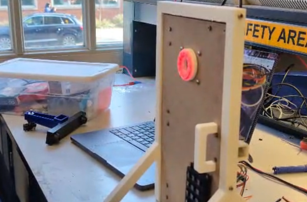
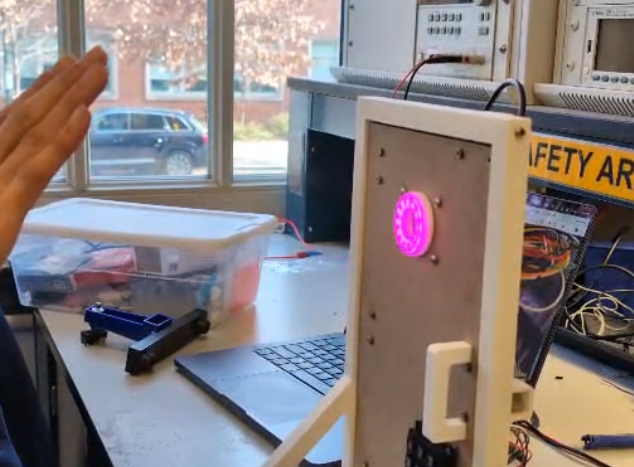
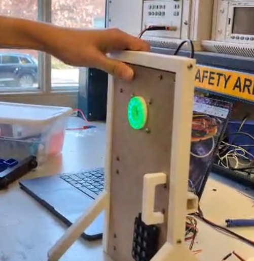
| SRS-LE-01 | The LED Ring shall change color or pattern depending on the current state: locked, unlocked, or waiting for verification. | Yes | Purple = gesture OK, Green = code OK, Red = default. |
Telegram Bot — Notifications and Interaction
| ID | Description | Completed (Yes / No / Partially) | Comments |
|---|---|---|---|
| SRS-TG-01 | The Telegram bot should receive messages from the ESP32 and show notifications to the user about lock, door, and presence events. | Yes | - |
| SRS-TG-02 | Notifications should include at least three event types: door opened/closed, person detected, and lock status change. | Partially | Presence-related notifications are missing because no presence sensor exists. |
| SRS-TG-03 | Each notification should be received in less than 10 seconds after the corresponding event occurs. | Yes | Messages typically arrive within ~4 seconds. |
6. Hardware Requirements Specification (HRS)
Formulate key hardware requirements here. Think deeply on the design: What must your device do? How will you measure this during validation testing? Create 4 to 8 critical system requirements.
These must be testable! See the Final Project Manual Appendix for details. Refer to the table below; replace these examples with your own.
6.1 Definitions, Abbreviations
Here, you will define any special terms, acronyms, or abbreviations you plan to use for hardware
6.2 Functionality
| ID | Description | Completed (Yes / No / Partially) | Comments |
|---|---|---|---|
| HRS-01 | Presence Sensor must be able to distinguish a human up to 3 meters away | No | Presence Sensor was never in stock and thus was a component we could not implement. Due to the overall complexity of the project we decided to focus on the other aspects of the project rather than wait and try to get the presence sensor |
| HRS-02 | Number pad shall be able to take a 6 digit input with each digit ranging from 0-9 | Partially | Instead of a 6 digit input we reduced it down to a 4 digit input for the sake of simplicity. However the number pad still gives the ability to enter in any digit ranging from 0-9. A 6 digit input is still possible and would just require a tweak in firmware |
| HRS-03 | Number pad shall have an additional input allowing the user to confirm their 6 digit input | Partially | Again the decision was made to do a 4 digit instead of 6 digit input. Within hardware the 6 digits are possible. As for the additional input, we do have the ability in hardware to do that but we decided that after 4 digits are inputted the input is confirmed. This reduces the amount of additional interaction required by the user. |
| HRS-04 | Ring LED must be able to cycle through at least 3 distinct colors | Yes | Can set each of the R,G, and B bytes individually. This means 256 levels of color change for each color resulting in 16777216 colors in total. |
| HRS-05 | Locking Mechanism must be locked by default even if power is disconnected | Yes | - |
| HRS-06 | Arduino Camera must be able to produce a video resolution of 60x60 | Yes | A resolution of 64x64 used |
| HRS-07 | Door Sensor shall be mounted in such a way that if the door is not fully closed the sensor will be able to detect it. | No | Reed switch has an distance of several centimeters where it reads as both on and off making detection in that range unknown. Thus making it not possible to mount in a way that both detects door status cleanly while also detecting a small opening in the door itself. Thus if the door is open by a few centimeters there is a chance that it will show as the door being open |
7. Bill of Materials (BOM)
What major components do you need and why? Try to be as specific as possible. Your Hardware & Software Requirements Specifications should inform your component choices.
In addition to this written response, copy the Final Project BOM Google Sheet and fill it out with your critical components (think: processors, sensors, actuators). Include the link to your BOM in this section.
8. Final Demo Goals
The final demo will show the complete operation of the dual-authentication smart door lock system. A miniature door frame will be 3D printed and a door will be laser cut out of MDF. The electronics will be mounted to various locations on the MDF door. The goal is to demonstrate a compact and functional prototype that combines gesture recognition, keypad verification, and real-time Telegram notifications.
Demo Scenarios
Case 1 – Full Success (Access Granted) The user performs a valid gesture that matches the trained model.The system recognizes the gesture, waits for the user to enter the correct code, and unlocks the door.The LED ring changes color to indicate the unlocked state.Three Telegram notifications are received:
- Lock: Door unlocked
- Door Sensor: Door opened
- Presence Sensor: Person detected nearby
Case 2 – Unrecognized GestureThe user performs a gesture that is not part of the trained model.The system does not enable keypad input or unlock the door.The LED ring remains in the locked color.Only one Telegram notification is received:
- Presence Sensor: Person detected nearby
Case 3 – Wrong Code after Valid GestureThe user performs a valid gesture, but enters the wrong code.The door stays locked and the LED ring does not change.Two Telegram notifications are received:
- Presence Sensor: Person detected nearby
- Lock: Access denied (door remains locked)
Physical and Environmental Notes
- The demo will use a 3D printed miniature Door Frame/Door Hinges and Laser Cut MDF Door to show real mechanical movement.
- Ring LED, Lock, Presence Sensor, and Number Pad will be mounted directly to various locations on the door. The rest of the electronics will be attached to a mounting plate at the back of the door and wiring will be routed from there. A circular cutout for the camera will be featured on the mounting plate and MDF door.
- Possible issue: weak or unstable Wi-Fi in the auditorium could delay the Telegram notifications.
9. Sprint Planning(ALL)
You’ve got limited time to get this project done! How will you plan your sprint milestones? How will you distribute the work within your team? Review the schedule in the final project manual for exact dates.
Fabian - ML/WiFi
Huan - Software Structure
Andy - Physical Hardware/Peripheral Firmware
| Milestone | Functionality Achieved | Distribution of Work (Fabian) |
Distribution of Work (Huan) |
Distribution of Work (Andy) |
|---|---|---|---|---|
| Sprint #1 | All critical systems(door lock and two authentication methods) implemented and working individually | Train and validate the gesture recognition model using Edge Impulse. Export and test model inference on Arduino to confirm gesture classification reliability before integration. | Design project architecture and file structure. Implement initial software flow in main.c | Write firmware/test hardware for all critical components(Door Lock and Number Pad) Door Lock, Ring LED, and Power Management circuits Implemented. |
| Sprint #2 | Critical systems integration started(at least one authentication method working and able to control door lock). Non critical systems(door sensor,ring led,presence sensor) working individually | Program ESP32 to send Telegram notifications through Wi-Fi. Implement message formatting for presence, door, and lock events. Validate latency and reliability of message delivery. | Integrate key firmware modules (e.g. initialization, I/O). Debug startup and runtime flow. Achieve stable core functionality. | Write firmware/test hardware for all non-critical components(Door Sensor, Ring LED, Presence Sensor) Complete CAD for door and door frame. |
| MVP Demo | Both authentication methods fully integrated and able to control door lock. Door and door frame demo is constructed with at minimum the door lock mounted and operational. Of the non critical components the ring LED and door sensor are also fully integrated. |
Integrate ESP32 and Arduino communication with ATmega328PB via digital signaling. Ensure that gesture and code results trigger corresponding Telegram updates. | Combine firmware and ML code. Debug full system and enable advanced features. Validate performance and functionality. | Construct door and door frame with lock and camera mounted. |
| Final Demo | All systems fully integrated with all hardware constructed | Finalize end-to-end functionality: ESP32 sends distinct Telegram notifications based on sensor events and lock status. Optimize message timing and Wi-Fi stability. Assist in final system debugging and demo presentation. | Ensure bug-free software and proper interrupt handling. Verify all modules work reliably. | Mount all components to the door and complete all wiring. |
This is the end of the Project Proposal section. The remaining sections will be filled out based on the milestone schedule.
Sprint Review #1
Last week’s progress
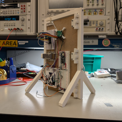
Andy - Mostly worked on the miniature door/door frame itself due to the lack of components for the majority of the week. Currently have and initial prototype of the door done. All CAD files, STLs, DWGs are committed to the git repo for further development.
We received parts towards the end of the week so I worked on getting the door lock hardware assembled and the number pad hardware working first. I was able to wired up the lock and drive it using the 328PB. The lock is currently mounted to the door itself and is we are able to use the 328PB to lock and unlock the door.
In addition to all that I wrote the initial firmware for interfacing with the number pad successfully. That code is also pushed to the git repo.

I also did some simple testing to make sure that the door sensor works as intended and that the buck converter is working as well. I also created a simple I2C program intended for ESP32 communication but that still needs work.

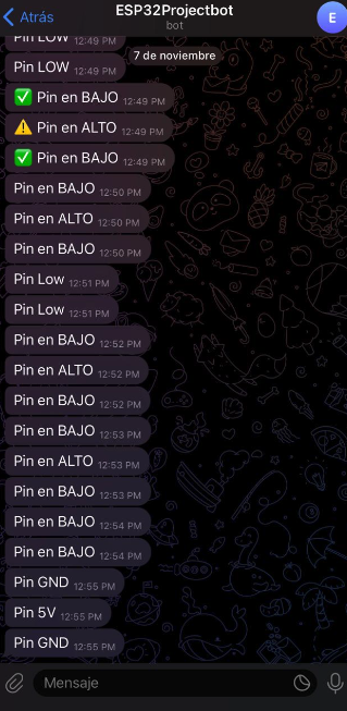
Fabian - This week I focused on establishing the first communication link between the ESP32 and the Telegram bot. Since the Arduino with the camera had not arrived yet and most components were still in the shipping process, I used the available ESP32-S3 to prototype the wireless notification system. I wrote a test program where the ESP32 monitors a digital input pin and immediately sends a Telegram message whenever the pin toggles between HIGH and LOW. This allowed me to verify Wi-Fi connectivity, message formatting, and the end-to-end notification path. The setup worked reliably, confirming that the ESP32 can send real-time updates based on external signals.
Huan - This week, I organized the hardware logic and built the overall driver framework. I also create main.c and hal.c to manage the whole project.
On the firmware side, I created the firmware files and header files needed for later use, collaborated with Andy to complete the integration of the numpad driver.
I also wrote the main.c and hal.c code to define the program’s execution flow. I also implemented the timer interrupt handler and the input interrupt handler.
Current state of project
Andy - Most of my parts for the MVP demo are almost there. I’ve written the firmware for the number pad which is one of our factors of authentication, the door lock circuit is built and tested, and we have an initial door prototype. The only thing left for me for the MVP demo is I2C communication with the ESP32. Besides the MVP demo I need to work on firmware for the ring LED as well as further improvements to the door itself.
Fabian - The ESP32–Telegram pipeline is already functional, meaning that wireless notifications are fully working in isolation. Once the ATmega328PB and ESP32 begin communicating through their digital interface, the system should be able to forward lock events, gesture results, and sensor updates directly to Telegram with minimal additional work. This puts the wireless subsystem in a stable state and ready for integration during next sprints.
Huan - The hardware logic has been reviewed and organized, providing a clear foundation for driver development. Created essential firmware files and header files for subsequent use. Collaborated with Andy to merge the numpad driver into the system. Implemented main.c and hal.c to define and stabilize the execution flow of the program. Developed the interrupt handler to manage periodic tasks and external signals efficiently.
Next week’s plan
Andy - I want to have the I2C firmware finished by next week. I am pretty confident that I will have it done by then and thus have everything I need done for the MVP demo. I also want to have the ring led mostly working by next week. From the documentation I think this will take a while as there is no designated protocol and its all bit banging to command the ring led. In terms of time line I think I can get some functionality before the MVP demo but probably not full functionality. The current door works but needs a bunch of adjustments. The door prototype is not needed for the MVP demo so I will put that off until everything else is done.
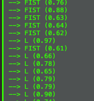
Fabian - Next week the main focus will be on starting the gesture-recognition pipeline. Now that the package with the Arduino camera has arrived, the first step is to set up the camera module and confirm that image capture works correctly. After that, I will begin collecting training data and building the gesture-recognition model using Edge Impulse. The plan is to support two distinct hand gestures, closed fist and “L”-shaped hand, so the system can reliably classify them as valid or invalid authentication attempts. The goal is to make steady progress on dataset collection, model training, and on-device inference so that gesture detection can be integrated into the system in the upcoming sprint.
Huan - Create a debug printer to facilitate future debugging and use macros to manage the debug function, and use this debug printer to ensure the simple password - lock system works properly. Work together with Andy to add more firmware drivers, like I2C and LED, to the library, hal, and main code.
Sprint Review #2
Last week’s progress
Fabian - This week I focused entirely on bringing the gesture-recognition pipeline closer to a usable form. I worked on understanding how the Arduino Nano BLE Sense Rev2 camera integrates with the Edge Impulse environment, including image acquisition, RAM usage, and on-device inference constraints. After several debugging cycles, I was able to capture images reliably and train multiple test models on Edge Impulse. Through experimentation, I confirmed that RAM is a major bottleneck: although the board has 256 KB, Edge Impulse restricts the model to roughly 70 KB of RAM, and any model above that threshold (e.g., the 80 KB version I attempted) fails immediately at runtime. I also validated that the camera update rate is another limitation, since the frame refresh is roughly one sample every three seconds, which slows down real-time inference. Despite these constraints, I successfully trained and deployed a working model capable of distinguishing between two classes: L-shaped gesture vs. closed fist. The on-device inference works, though slow, confirming the full pipeline (camera → Edge Impulse model → Arduino inference) is functional.
Huan - Last week I successfully completed the driver code for the LED, NUMPAD, and lock modules and integrated them into main.c. After thorough debugging, the password lock feature is now functioning as intended. The system can respond to password input by controlling the LEDs, which flash in different colors depending on whether the input is correct or incorrect.
Andy - This week was spent getting the firmware for the I2C protocol finished along with the Neopixel ring LED. For I2C, I wrote the bare metal C firmware on the server side which is for the the 328PB. It allows us to manually select an address and send a byte of data. That byte is able to tell the client side the status of the door itself if there are any status changes. I also modified Fabian’s ESP32 code so it includes the client side I2C software. For that the EPS32 reads what the 328PB sends and stores it for transmission over the wireless module to the user’s phone. Here is a link to a video of that working. The 328PB is sending over data packets while the ESP32 prints those data packets out over serial. That print will be replaced with a wireless transmission of data.
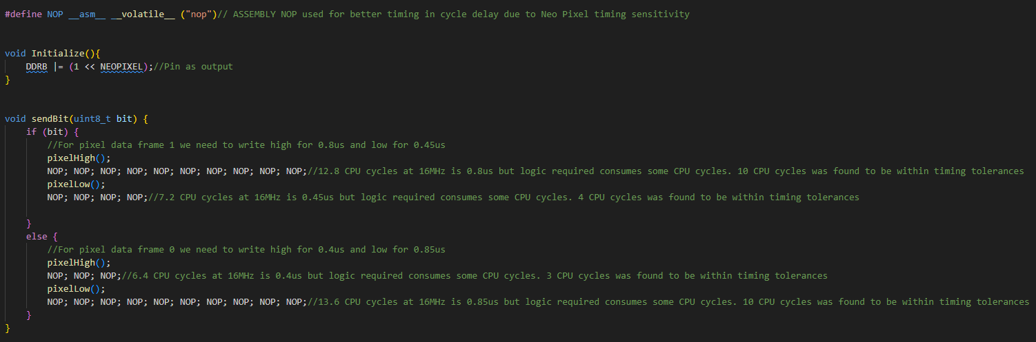
The other firmware that I worked on extensively is the LED driver firmware. We are using a Neopixel ring led with 12 included LEDs. Specifically these leds use WS2812B LEDs or SKC6812 LEDs which from a firmware perspective are all the same in terms of protocol. This firmware was the hardest to develop. These LEDs do not use a standardized protocol and instead require bit banging over a single data line with very strict timing requirements. I started out trying to just toggle the pin on and off in a loop with a timer delay but with all of the higher level logic, the timing was way to inconsistent. More often than not the LEDs would just turn white as it wasn’t getting the proper data signal. Based on this I realized that we can’t just use normal logic and timers. The solution was to use Assembly as that gives us even lower level control over the exact timings. To do this I hardcoded NOPs which we know for certain consume exactly one CPU clock cycle and from there we can hard code a high or low data bit by sending a consistent stream of NOPs while the GPIO pin is low or high.
This however only lets us send a single bit. From there we need to send bytes. The original plan was to use a for loop and a moving byte mask to use sendBit within the loop was the byte mask reads bits out from MSB to LSB. The loop itself consumed too much time and thus the send byte had to also be hardcoded.
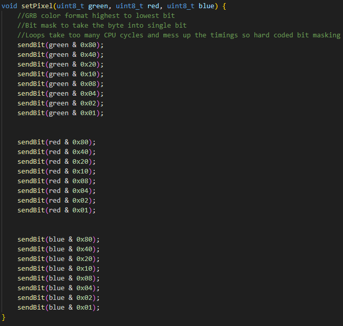
To sum it up due to the strict timing nature of the Neopixel LEDs I spent a lot of time trying to think of ways to have a consistent method of bit banging the data stream. This link is a video of multiple LED animations that can be use or programmed for the over all project.
Beside the firmware that I wrote, I also did a full scale test of the electronics hardware. I was able to power the LED, Arduino, 328PB, ESP32, and Solenoid off of one power supply. That power supply gives 12V and the buck converter was able to handle the load for the rest of the 5V peripherals.
Current state of project
Fabian - At this point, both wireless and vision subsystems are operational in isolation. The ESP32 continues to function reliably as a notification module, and the gesture-recognition model, though limited by memory and frame rate, is producing correct classifications. The next integration step is preparing the interface between the ESP32 and the ATmega using I²C. The team has defined a consistent message protocol, and I will implement the ESP32 side of this communication.
Huan - At present, the password lock module is fully operational and works perfectly. The door sensor, I²C communication, and ESP32 integration remain outstanding, so the project is not yet complete but is progressing toward its final form.
Andy - Currently, all of my firmware and electronics hardware is done and ready for the MVP demo. I worked with Huan and Fabian and we did a almost full scale integration test. All that’s missing is the integration of what Huan has mentioned.
Next week’s plan
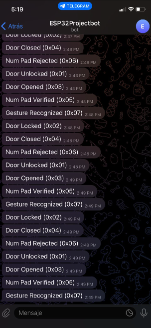
Fabian - Next week I will focus on implementing and validating the I²C communication from the ESP32 to the ATmega328PB, ensuring that every system event is transmitted using the designated message codes. The goal is for the ESP32 to reliably send lock, door, numpad, and gesture updates with minimal latency so they can be forwarded to Telegram in real time. Once this task are completed, the wireless subsystem will be ready for integration into the MVP demo. The final messages will include:
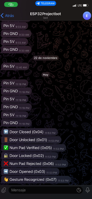
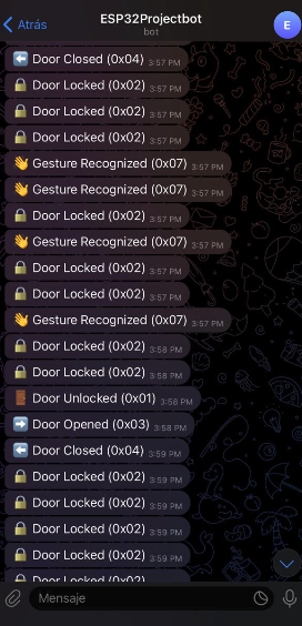
0x01 Door Unlocked 0x02 Door Locked 0x03 Door Opened 0x04 Door Closed 0x05 Num Pad Verified 0x06 Num Pad Rejected 0x07 Gesture Recognized
Huan - Next week the focus will be on implementing and testing the door sensor, developing the I²C communication module, and establishing ESP32 connectivity. Once these components are integrated with the existing password lock system, the project will reach the stage of a complete MVP demo.
Andy - Next week will be focused on supporting Huan in integrating everything. He will be using the firmware drivers that I initially wrote and needs to further develop them into his own code. I will also start work mounting/door redesigns in preparation for the Final Project Demo.
MVP Demo
- Show a system block diagram & explain the hardware implementation.
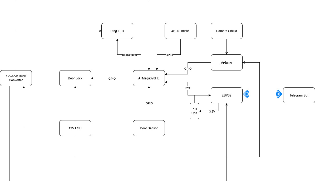
Here is the new updated system block diagram for the hardware. For the most part everything is basically the same. Power distribution stays the same except for two notable changes. First a 12V to 5V buck converter is added to the diagram. It was in our original design, just not explicitly stated in the diagram. Next is that the Arduino is pulling voltage directly from the 12V PSU. Its Vin pin can handle up to 22V. We found that the 5V buck converter cannot provide enough current. The converter can only provide up to 1.2A which the Ring LED already consumes around 720mA at full brightness. The Arduino at full load can consume up to 1 Amp. So not even factoring in the ATMega we are beyond the 1.2A that the converter can provide. Thus we tied the Arduino directly to the 12V PSU. The ESP32 and ATMega328PB do not consume enough of the 5V power to push it beyond 1.2A in addition to the max current consumption of the Ring LED. Another major change is the removal of the presence sensor as it was out of stock. The final change is the explicit statement of the I2C pull up resistors. We are using a 3.3V Vcc for the I2C pull up. The ESP32 has a 3.3 Vcc while the 328PB has a 5 Vcc. Thus we cannot drive the I2C line to 5 Vcc as that would damage the ESP32. However 3.3V is fine as the ESP32 can handle it and the 328PB logic level high threshold is 3V. Thus we can use 3.3V without a level shifter.
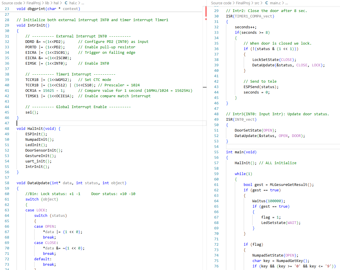
- Explain your firmware implementation, including application logic and critical drivers you’ve written.
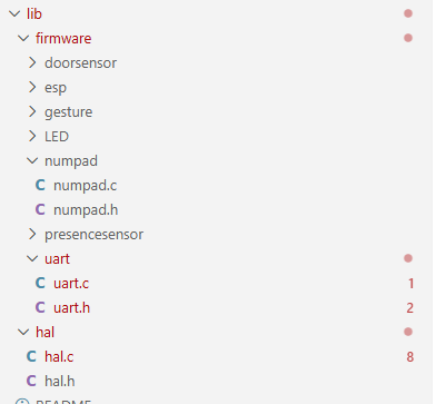
The project’s codebase is structured into a three-layer architecture to ensure clear separation of concerns and maximum decoupling between modules.
(1)Architectural Layers
- Bottom Layer: Firmware Driver Layer
This layer is responsible for the unified management of all low-level hardware drivers. It provides an abstracted interface for the hardware.
- Middle Layer: Hardware Abstraction Layer (HAL)
The HAL (hal.c) is where the critical drivers and core control logic reside. It handles the low-level register configuration (specifically for the ATmega328PB micro-controller) and performs fundamental data processing tasks required for the application’s basic control functions.
- Top Layer: Application Logic Layer
The main.c file implements the complete project workflow by utilizing the higher-level functions exposed by the HAL.
This layered approach is a key design decision. It promotes modularity and maintainability, ensuring that changes to the low-level register configurations in the HAL do not propagate and affect the application-level functions in main.c.
(2)Application Logic in main.c The application logic follows a state-based sequence:
- Gesture Authentication: The system first evaluates a specific gesture input.
- Number Pad Enable: Upon successful gesture authentication, the number pad is enabled, and the system waits for the user to input a password.
- Unlock Mechanism: The system is unlocked when the entered password matches the stored credentials.
- Automatic Re-lock: A critical safety feature is implemented with a 18-second timeout. If the door is detected to be closed and is not locked after this period, the system automatically engages the lock mechanism.
(3)Critical Driver Implementation
- For the LED driver we used Assembly for the bit banging. NeoPixels have tight timing restrictions so Assembly was the most reliable way to ensure good timing. The firmware to send the data used hard coded masking to send the bits using Assembly as for loops and if statements would mess up the timing. On top of that is the regular logic to figure out what bytes we want to send. That higher level logic does not affect the timing as only when we send bytes via bit banging do the timings matter. Thus in firmware we can program LED animations to the Ring LED by sending the appropriate GRB bytes.
- For the Number Pad, we use a scanning method. The column GPIO ports are all set high except one pin. All row GPIO ports are set to be inputs. Thus when the button is pressed it connects a column with a row driving that row low. Thus if we scan through the columns our logic is the following. Depending on the current column being set low, which row is being pulled low. This decodes a row and column that are connected. From that we just have to output the associated button value being pressed. The firmware also has a delay to act as a debouncer.
- For the Door Sensor, we use input interrupt to get the pin status and it indicates whether the door is opening or closed. We further update the data and transfer it to the remote device.
-
Demo your device.
Demoed to teaching staff (Kevin).
-
Have you achieved some or all of your Software Requirements Specification (SRS)?
Most of the Software Requirements Specification items have been fully implemented. The ATmega correctly satisfies SRS-AT-02 , SRS-AT-03 , and SRS-AT-04 , managing the full authentication sequence and updating the ESP32 with minimal delay. Gesture detection successfully fulfills SRS-GE-01 and SRS-GE-03 , completing the end-to-end pipeline from camera capture to classification. The keypad subsystem meets SRS-NP-01 and SRS-NP-02 , allowing the user to enter a code and validating it on the ATmega. The door sensor requirement SRS-DR-01 is fully functional, and the LED ring requirement SRS-LE-01 is met, with the LEDs reflecting the system state correctly. The ESP32 notification module achieves SRS-ES-01 , and the Telegram system goes beyond SRS-TG-01 , SRS-TG-02 , and SRS-TG-03 , sending seven different notification types instead of just the required three.
Some requirements were intentionally changed or removed. All presence-related requirements— SRS-PR , SRS-AT-01 (presence portion), and SRS-PR-01 —were discarded because the ultrasonic sensor was out of stock, so presence detection is no longer part of the system. The accuracy requirement SRS-GE-02 could not be met due to hardware limitations: the camera captures a frame roughly every 3 seconds, and Edge Impulse restricts RAM to about 70 KB, preventing us from running larger or more robust models. The lockout requirement SRS-NP-03 was modified intentionally: instead of a 5-second block after three failed attempts, we implemented a 10-second lockout to provide clearer feedback during testing. Aside from these changes, the system fulfills the majority of the SRS, and any deviations were caused by hardware constraints rather than design issues.
Show how you collected data and the outcomes.
- Number Pad Data Collection (User Input) Collection Method: User input is collected directly via the physical key presses on the number pad matrix.To ensure data accuracy and prevent errors, we implemented software debouncing logic. This code filters out transient signals generated when a mechanical key is pressed or released, effectively preventing a single physical press from being registered as multiple accidental inputs.
-
Door Sensor Data Collection (Door Status) Collection Method: We utilized a magnetic switch (likely a reed switch) as the door sensor. The door’s state is determined by the proximity of the magnet.
Door Closed: When the magnet is in close proximity to the switch (i.e., the magnets are “attracting” or aligned), the circuit is completed, indicating the door is closed.
Door Open: When the magnet is moved far away from the switch, the circuit is broken, indicating the door is open.
-
System Outcomes (Password Check Feedback) Method: The outcome of the password check is provided to the user via a change in an LED indicator’s color.
Correct Password: The LED turns Green to confirm successful authentication.
Incorrect Password: The LED turns Red to indicate a failure in the password attempt.
-
Gesture Recognizing:
Arduino:
Esp32:
- Have you achieved some or all of your Hardware Requirements Specification (HRS)?
Due to the presence sensor not being in stock we were not able to meet any of the presence sensor requirements as that was removed from the project.
HRS-02 is partial met. The 4x3 input number pad gives us digits 0-9 as well as 2 extra input buttons. However we decided that a 6 digit input is a bit too long and that a 4 digit input was enough
HRS-03 is not met. We decided to scrap this requirement in the end and just have the confirmation happen once all digits are entered. It makes it so that there is one less input to deal with both on an implementation and a user standpoint
HRS-04 is met. NeoPixels can do 8 bit RGB color. Our firmware uses all three colors and even mixes colors together. Through the testing of the LED firmware we confirmed that we can output 3 distinct colors
HRS-05 is met. The solenoid by default is off. The circuit built uses a BJT to drive the 12V to the solenoid. Due to the spring in the solenoid, when the lock is not powered, the slug naturally is pushed outwards by the spring. When we drive 12V using the GPIO pin and BJT, the solenoid engages and pulls the slug back, thus unlocking the door when powered and locking the door when un-powered.
HRS-06 is met. Via the Arduino script the video settings are always outputted on the program start and state a 64x64 resolution for the camera.
HRS-07 is not met. This is part of the mechanical case work and not necessary for the MVP demo so we’ve put it off for now. This will be ready for the final demo itself.
6.Show off the remaining elements that will make your project whole: mechanical casework, supporting graphical user interface (GUI), web portal, etc.
The remaining elements that complete the project are the mechanical enclosure and the user interfaces that tie the system together. The physical interface is formed by the keypad mounted on the door and the mechanical door/lock assembly, which allow the user to interact with the authentication system directly. On the software side, the Telegram interface acts as the main GUI, displaying all system events, lock status, and sensor updates in real time.
Improved CAD design for door. We currently have a door built but with the exception of the door lock it does not have holes for mounting. This is the current progress for a new version that will have mounting points for everything.
-
What is the riskiest part remaining of your project?
- The Arduino so far has been a bit tricky in terms of powering on and starting the ML. When powering it externally without USB it sometimes works but most of the time does not work. We think that maybe the USB needs to be plugged in on boot-up but after that it should be fine. It needs more testing. Without USB we also don’t know what the ML is seeing or if it is even trying to capture something as well. To mitigate this risk we will try and understand the actual startup procedure. Failing that we will just have USB plugged into the Arduino the entire Final Demo Session.
- I2C when integrated with the entire system causes many issues. This is the last major issue we are experiencing so we will try and get it working before the actual demo. If not we will just abandon it for the demo.
- Power distribution is another risk: the system combines an ATmega, ESP32, Arduino Nano BLE Sense, a solenoid lock, and a LED ring, all running from the same supply. If the current draw spikes, the micro-controllers could brown-out or I²C communication could become unstable.
- The physical integration of all components into the door model must be done carefully; loose connections or mechanical stress on the wiring could cause intermittent behavior.
-
What questions or help do you need from the teaching team?
Final Project Report
Don’t forget to make the GitHub pages public website! If you’ve never made a GitHub pages website before, you can follow this webpage (though, substitute your final project repository for the GitHub username one in the quickstart guide): https://docs.github.com/en/pages/quickstart
1. Video
- The video must demonstrate your key functionality.
- The video must be 5 minutes or less.
- Ensure your video link is accessible to the teaching team. Unlisted YouTube videos or Google Drive uploads with SEAS account access work well.
- Points will be removed if the audio quality is poor - say, if you filmed your video in a noisy electrical engineering lab.
2. Images
400x400 Images:
3. Results
3.1 Software Requirements Specification (SRS) Results
The final implementation meets the majority of the intended software requirements, although several specifications were modified or only partially satisfied due to hardware limitations, unavailable sensors, or architectural decisions made during integration. Despite these constraints, the system remained stable, responsive, and consistent with the project’s security goals.
Most core requirements, ATmega sequencing, keypad verification, door sensor updates, LED state transitions, and Telegram notifications, were fully achieved. The gesture-recognition pipeline also works end-to-end, though limited by RAM and camera frame rate. Requirements related to the presence sensor were removed because the ultrasonic module never arrived. Timing requirements for gesture recognition and keypad timeout were partially met or modified due to practical design constraints.
Below is a summary and validation of key software requirements. Validation images and short videos are included in the Results section, and the full demo video (linked above) shows the system’s behavior in real time.
Validated Requirements
| ID | Description | Validation Outcome |
|---|---|---|
| SRS-DR-01 | Detect door open/close and send a Telegram notification. | Validated. Door sensor triggers updates instantly; ESP32 forwards notifications within ~4 seconds. Screenshots and demo video confirm correct operation. |
| SRS-LE-01 | LED Ring shall display system state (locked, unlocked, waiting). | Validated. LED transitions are synchronized with state changes; photos in Results show correct colors. |
| SRS-NP-02 | Each keypad press sends a signal to the MCU for validation. | Validated. Debounced scanning matrix detects each key reliably; LED feedback proves correct state transitions. |
Requirement Changes
- All presence-related requirements (SRS-PR, SRS-AT-01 presence portion, SRS-PR-01) were removed because the sensor became unavailable.
- Gesture accuracy requirement (SRS-GE-02) was not met due to strict 70 KB RAM limits imposed by Edge Impulse on the Arduino.
- Keypad timeout and lockout (SRS-NP-01, SRS-NP-03) were simplified: no timeout is used, and failed attempts require a new gesture instead of a timed lockout.
These changes were required to ensure the system remained functional and stable given the available hardware.
Proof of Work
Below is a sample of supporting evidence included in the Results section:
Telegram Notifications: Screenshots showing real-time door open/close messages and lock/unlock events.
LED Ring State Changes: Images demonstrating purple (gesture OK), green (correct code), and red (default/locked).
End-to-End System Validation: The final demo video contains continuous footage proving the interaction between the camera, keypad, ATmega sequence, LED transitions, door sensor, and Telegram notifications.
These results confirm that the system delivers a complete dual-authentication workflow with real-time feedback and remote monitoring.
3.2 Hardware Requirements Specification (HRS) Results
Based on your quantified system performance, comment on how you achieved or fell short of your expected requirements.
Did your requirements change? If so, why? Failing to meet a requirement is acceptable; understanding the reason why is critical!
Validate at least two requirements, showing how you tested and your proof of work (videos, images, logic analyzer/oscilloscope captures, etc.).
For additional explanation of each HRS and their outcome please refer to the HRS table in the previous sections of this README
All validation videos include audio commentary that go into each HRS in more depth.
| ID | Description | Validation Outcome |
|---|---|---|
| HRS-01 | Presence Sensor must be able to distinguish a human up to 3 meters away | Requirement not meet, no validation (See HRS Table above/Explanation below) |
| HRS-02 | Number pad shall be able to take a 6 digit input with each digit ranging from 0-9 | Validation can be viewed in this-video |
| HRS-03 | Number pad shall have an additional input allowing the user to confirm their 6 digit input | Requirement not implemented, alternative method used instead, no validation (See HRS Table above/Explanation below) |
| HRS-04 | Ring LED must be able to cycle through at least 3 distinct colors | Validation can be viewed in this-video |
| HRS-05 | Locking Mechanism must be locked by default even if power is disconnected | Validation can be viewed in this-video |
| HRS-06 | Arduino Camera must be able to produce a video resolution of 60x60 | Validation can be viewed in this-video |
| HRS-07 | Door Sensor shall be mounted in such a way that if the door is not fully closed the sensor will be able to detect it. | Validation can be viewed in this-video |
We meet most of our Hardware Requirements. Out of the 7 that we had only two of them we were unable to meet. HRS-01 and HRS-07 were the ones we were not able to meet. HRS-01 was unmet due to being unable to obtain the presence sensor as it was out of stock and thus we decided to focus on implementing everything else. HRS-07 was unmet due to some physical aspects of the door sensor. The door sensor itself is a reed switch so it electromagnetically senses if the door is open or not. This creates a region in which when the door is semi open it jumps between a switch open and closed output making it difficult to mount it in a way that avoids this unknown state. Thus we are left with a specific state that the door can exist in where the door is slightly open but the sensor states that the door is closed.
For all other Hardware Requirements we were able to meet or had to modify slightly. This is the case for HRS-02 and HRS-03. HRS-02 talks about a 6 digit input with each digit ranging from 0-9. Our firmware and hardware are able to take a 6 digit input and each digit ranging from 0-9 but we decided for the sake of simplicity to reduce the passcode down to 4 digits. Thus the ability for HRS-02 is capable within the hardware as it has numbers 0-9 and there is no limitation physically on the length of the input. We capped it to 4 digits within firmware for ease of use rather than some external factor. As for HRS-03 the hardware featured two non digit buttons, a * and a #. Those classify as an additional input that allows the user to confirm their input. However we scrapped that functionality within firmware, again for the sake of simplicity where if the number of inputs equals the number of digits in the passcode it would be considered as entering in the passcode. Our firmware supports the additional two buttons as does the hardware so technically the hardware requirement is meet but for implementation’s sake we did not utilize those buttons as methods for confirming the input. All other requirements were meet with not issue or having to sacrifice any thing else.
4. Conclusion
Reflect on your project. Some questions to address:
- What did you learn from it?
One of the most significant experience was managing power distribution in integrated systems. We learned that total current consumption (especially under full LED brightness and heavy processing loads) can easily exceed the limits of standard buck converters, forcing a shift to pull power directly from the PSU for the Arduino. From the Arduino’s schematics it showed that the on board power management can accept up to 21V as the input voltage. Thus it allowed us to pull power directly from the 12V supply rather than add to the current consumption of the buck converter. We got lucky in this scenario that our 12V supply could be used with the Arduino. However in the future we would calculate our power consumption more carefully and choose the proper buck converter in the future.
We also encountered a hardware bottleneck with the door reed switch, discovering a “dead zone” where the sensor reported the door as closed even when slightly open. Additionally, the gesture-recognition pipeline was constrained by available RAM and camera frame rates, highlighting the performance trade-offs inherent in embedded machine learning. We also learned about the difficulties of bit banged communication protocols. The NeoPixel driver utilized a custom one wire communication protocol for setting the LEDs. Unlike I2C or SPI its not a standardized serial protocol. Instead we had to learn how to interpret the proprietary protocol from the data sheet and implement it with tight timing restrictions ourselves.
- What went well?
Layered Firmware Architecture: Using a three-layer decoupled structure (Firmware, HAL, Application) successfully separated hardware complexity from the state logic, making the code much easier to maintain.
Timing-Critical Implementation: Writing the NeoPixel driver in Assembly was a successful strategy for ensuring bit-banging precision within the tight timing requirements of the LED ring. We learned to use NOP instructions within the bare-metal C firmware. NOPs execute one CPU cycle exactly which allow us to control the timing of how long the line is high and low for. All put the NeoPixel driver was quite consistent allowing the higher level firmware to just write GRB bytes to the NeoPixel driver and the driver is able to take that and command the NeoPixel properly.
Communication: Merging I2C lines between the ESP32 and ATmega328PB by using 3.3V pull-ups worked perfectly to protect the ESP32 while meeting the logic-high threshold for the 328PB. This allowed us to avoid the use of a level shifter. Its not ideal but the logic high voltage on the 328PB is lower than 3.3V which means that for this application we can get away with out using a level shifter.
- What accomplishments are you proud of?
We are particularly proud of the end-to-end integration of disparate systems—combining computer vision (gesture recognition) with manual user interaction (keypad) and wireless notification (Telegram) into one stable, responsive sequence. We have 3 different MCUs each one doing their own specific task and they were all able to execute their given tasks and successfully communicate with each other to achieve the end goal.
- What did you learn/gain from this experience?
We gained valuable experience in integrated embedded system design, specifically:
Deep Understanding of Power Management: We learned that meticulous current budgeting is essential in high-power consumption systems (like those with bright LEDs and micro-controllers), quickly hitting the limits of standard converters and necessitating direct PSU connections for certain components.
Practical Firmware Architecture: We mastered how a three-layer decoupled architecture (Driver, HAL, Application) effectively separates hardware complexity from application logic, greatly enhancing the code’s maintainability and modularity.
Timing-Critical Code: We practiced using Assembly for bit banging operations (specifically for the NeoPixel driver) to ensure reliable system timing.
We also gained valuable experience in developing firmware and hardware in a group setting. By carefully isolating and distributing specific tasks in the planning phase we ensured that no one member’s progress was blocked by another member. In addition to that, by having constant communication between group members we ensured that the firmware we each wrote would be able to communicate with the other’s firmware.
- Did you have to change your approach?
Initially, We planned for an ultrasonic presence sensor, but due to stock issues, we had to pivot the system design to skip the presence detection phase. We also simplified the user experience by reducing the passcode from 6 digits to 4 and automating the verification process (removing the need for the ‘#’ or ‘*’ keys) to make the physical prototype more user-friendly during testing.
- What could have been done differently?
Sensor Selection: Finding a more precise door switch to eliminate the unknown “semi-open” state.
Hardware Sourcing: Having an alternative sensor list early on to prevent the total loss of features (like the presence sensor) when parts are out of stock.
- Did you encounter obstacles that you didn’t anticipate?
Current Overload on Converter: The biggest surprise was the inadequate current capacity of the 5V buck converter, which was quickly maxed out by the Ring LED and Arduino, forcing an unexpected architectural change to power the Arduino directly from the 12V supply.
Door Sensor “Blind Zone”: The door reed switch created an undefined state where the sensor output toggled between open and closed when the door was only partially ajar. This was a physical challenge related to mounting and the inherent nature of the sensor.
Hardware Unavailability: The ultrasonic presence sensor was out of stock, forcing us to completely remove a specified feature (HRS-01) without a viable replacement, leading to a required scope change.
- What could be a next step for this project?
The logical next step is to optimize the Machine Learning pipeline to increase the camera frame rate and recognition accuracy, potentially moving some of the processing to a dedicated vision coprocessor to alleviate RAM constraints. We would also consider both firmware and hardware security designs. This project was an initial look into a 2 factor authentication entry way. We could swap out some factors for something more secure like an RSA key or a finger print sensor. The firmware does include WiFi which does allow for a vector of attack from the outside. The lock system is also quite simple. The solenoid just uses a simple dead-bolt and catch to ensure a locked door. A higher powered electromagnet or other system could be implemented for a more mechanically secure lock. Implementing that would also require a much more complex power distribution system.
References
Software Libraries Used (ESP32 Firmware)
This project uses several core Arduino-ESP32 framework libraries to enable Wi-Fi connectivity, HTTP communication, I²C messaging, and asynchronous task management. Below is a list of all libraries referenced in the ESP32 firmware, along with their purpose in the system.
1. WiFi.h
Purpose: Provides Wi-Fi interface control for the ESP32.Used for:
- Connecting to the Wi-Fi network in station mode
- Managing connection retries
- Powering off the Wi-Fi radio after each message to reduce load
Key API calls: WiFi.mode(), WiFi.begin(), WiFi.disconnect(), WiFi.status()
2. HTTPClient.h
Purpose: Implements HTTP GET/POST operations for interacting with remote APIs.Used for:
- Sending Telegram Bot API messages through HTTPS URLs
- Encoding custom event messages (lock, door, keypad, gesture notifications)
Key API calls: http.begin(), http.GET(), http.end()
3. Wire.h
Purpose: Arduino I²C library for master/slave communication.Used for:
- Configuring ESP32 as an I²C slave at address
0x20 - Receiving 1-byte event codes sent by the ATmega328PB
- Handling incoming data via interrupt callback
Key API calls: Wire.setPins(), Wire.begin(), Wire.onReceive(), Wire.read()
4. string.h
Purpose: Standard C string utility library.Used for:
- Safely copying messages into a volatile shared buffer
- Ensuring proper null-terminated strings before passing to the Telegram sender task
Key API calls: strncpy()
5. fsanderh-project-1_inferencing.h
Source: Edge Impulse (auto-generated)Purpose:
- Contains the machine learning model.
- Runs the classifier (
run_classifier()function). - Defines the input size, labels, and model settings.
Why it is needed: It allows the Arduino to run the gesture recognition ML model.
6. Arduino_OV767X.h
Source: Official Arduino library for OV7670/OV7675 camerasPurpose:
- Starts and configures the camera.
- Captures image frames.
- Gives the frame size and pixel format.
Why it is needed: It allows the Arduino to read images from the camera and send them to the ML model.
7. stdint.h
Purpose:
- Provides fixed-size data types like
uint8_t,uint16_t,uint32_t.
Why it is needed: Image pixels and buffers require exact-size types for correct memory handling.
8. stdlib.h
Purpose:
- Provides memory functions like
malloc()andfree()(used insideei_mallocandei_free).
Why it is needed: The program allocates memory for image buffers before running the ML model.