final-project-website-submission-f25-t08-f25-g_square
e-Puppy
Final Project Report
1. 🎥 Video
2. 📸 Images
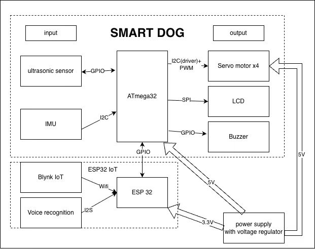
3. 🎨 System Block Diagram
4. 🤔 Results
Since suitable speech-recognition libraries were unavailable and the ESP32 did not have enough memory for audio processing, we replaced word control with a clap detection module. The microphone listens for claps, identifies the pattern, and sends the corresponding motion(stand, prone, forward and backward) to the ATmega328PB.
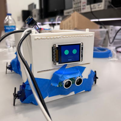
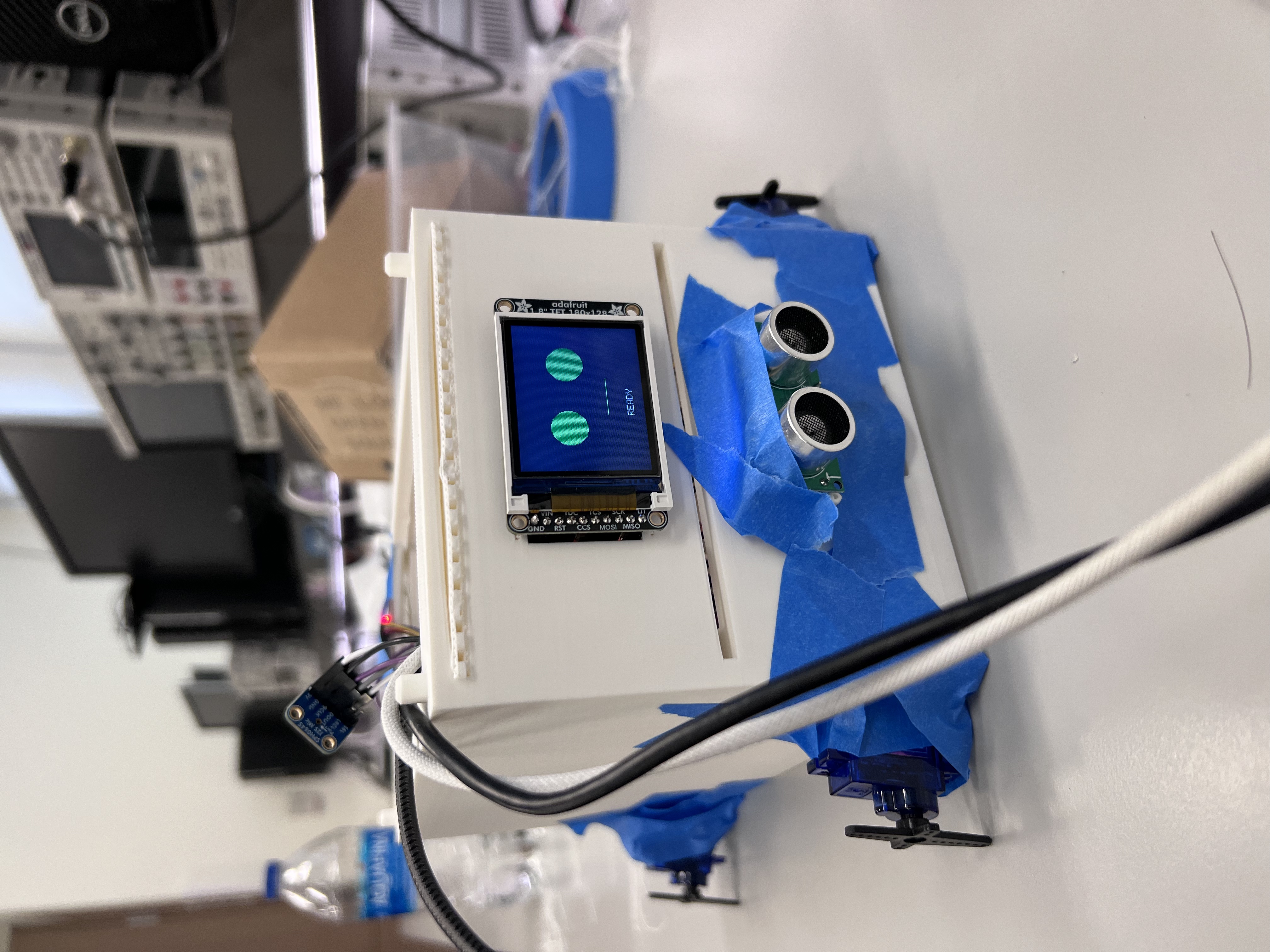
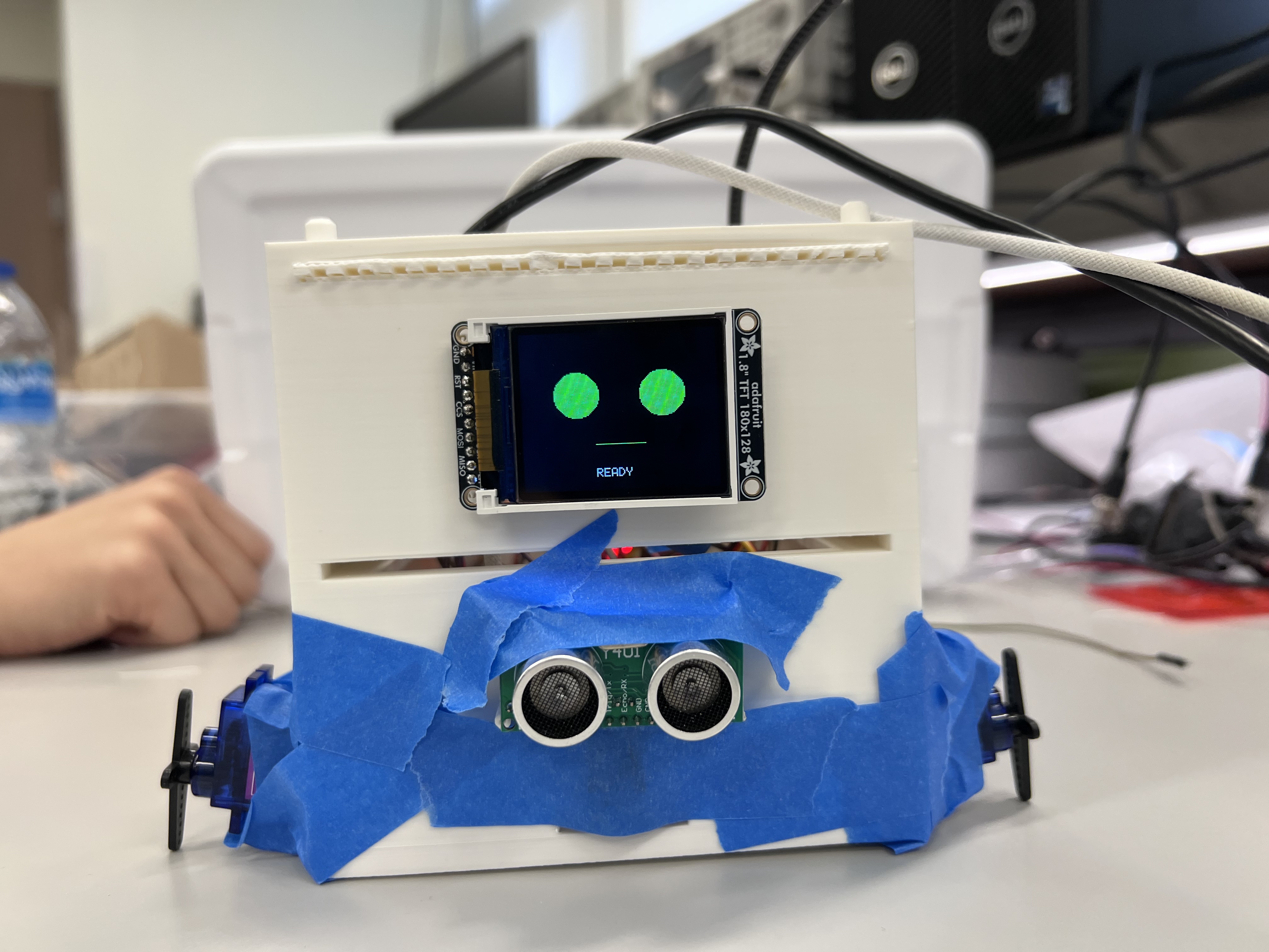
The dog also uses an ultrasonic sensor to detect nearby obstacles; if something is closer than 20 cm, the robot stops and activates a warning buzzer. An LCD display updates every second to show facial expressions that represent the dog’s current action, such as walking and sitting.
The ESP32 provides remote-control capability by sending system commands to the Blynk IoT platform. In addition, the IMU continuously measures acceleration, and if it detects movement beyond a safe threshold, the system triggers an emergency stop.
4.1 Software Requirements Specification (SRS) Results
| ID | Description | Validation Outcome |
|---|---|---|
| SRS-01 | The microphone module shall continuously listen for claps and identify the number, then send recognized data to the ATmega328PB. The command shall be verified against the stored command set and corresponding actions will be triggered immediately. | Confirmed via live testing and video evidence. |
| SRS-02 | The ultrasonic sensor shall measure the distance every 1 s. If an obstacle is detected within 20 cm, the robot stops movement and triggers the buzzer to emit a warning signal. | Confirmed via live testing and video evidence. |
| SRS-03 | The LCD display shall update every second to show facial emotions corresponding to the robot’s current action (e.g., sit, walk, stop). | Confirmed via live testing and video evidence. |
| SRS-04 | The ESP32 shall transmit system command to the Blynk IoT platform for remote control. | Confirmed via live testing and video evidence |
| SRS-05 | The IMU shall continuously measure 3-axis acceleration and send data to the ATmega328PB via I2C. When the acceleration exceeds a predefined threshold, the system shall issue a email alert via the IoT platform. | Confirmed via video evidence and serial output. |
4.2 Hardware Requirements Specification (HRS) Results
| ID | Description | Validation Outcome |
|---|---|---|
| HRS-01 | The ESP32 shall measure the number of claps using a microphone and send the recognized count to the microcontroller. Each number triggers a physical action such as sit, walk, or prone. | Partially confirmed via live testing and video evidence. Clap recognition and command triggering were validated, but the walking motion was limited by mechanical design and low friction between foot and ground. |
| HRS-02 | Four servo motors shall be used to perform limb movements. The servos receive PWM control signals from the microcontroller and operate smoothly with a positional accuracy of ±2°. | Confirmed via live testing and video evidence. |
| HRS-03 | An ultrasonic sensor shall measure the distance to obstacles in front of the robot. If an object is detected within 20 cm, the system stops motion and activates the buzzer. | Confirmed via live testing and video evidence. |
| HRS-04 | The ESP32 shall provide IoT connectivity through the Blynk platform, enabling remote basic control via a mobile application. | Confirmed via live testing and video evidence |
| HRS-05 | The LCD display shall show expressive facial emotions corresponding to the robot’s current action, providing visual feedback to the user. | Confirmed via live testing and video evidence |
| HRS-06 | An IMU sensor shall measure 3-axis acceleration and communicates with the microcontroller via I2C. | Confirmed via video evidence and serial output. |
5. ✍️ Conclusion
Yubin
From the final project, I learned how to programme communication protocols and integrate multiple modules. I was responsible for IMU programming and system integration. While individual modules worked well, integration introduced challenges.
Initially, we used an ADC-based microphone on the ATmega, which worked in isolation but failed once the ultrasonic sensor, IMU, and buzzer were added. After consulting with the TA, we switched to an I2S-based solution using ESP32. We later identified blocking delays as the main issue and resolved it using timers.
In the future, we plan to improve motion smoothness and revisit voice-recognition control using spoken commands.
Haoliang
I learned how to use a mircophone to detect the voice information using I2S protocol, and leverage it to control the LCD and servo motors. Also, I have known better about the bare metal program. It is kind of overwhelmed when we use it to tackle a lot of tasks. So next time I may use RTOS instead of bare metal. For me, the ultra sonic and the LCD works well. I am proud of the voice control, which recognizes the number of claps as orders and the cooperation of the four servo motors. I think the walking motion could have been done differently since we could produce another PWM to drive the motors or stick something to the legs to enhance the friction if we have one more day. One obstacle is that it was harder than we thought to use "words" to control the dog. After we tried two ways, we gave it up and chose the claps. But on the Demo day I saw another team had sucessfully implemented the function. I asked them and they told me that they used a voice module which they found in Dektin. So next time we should explore the Detkin carefully. For the next step, I think we can try a different PWM to drive the motors to see if the legs can sucessfully move the body, or enhancing some friction.
Shengge
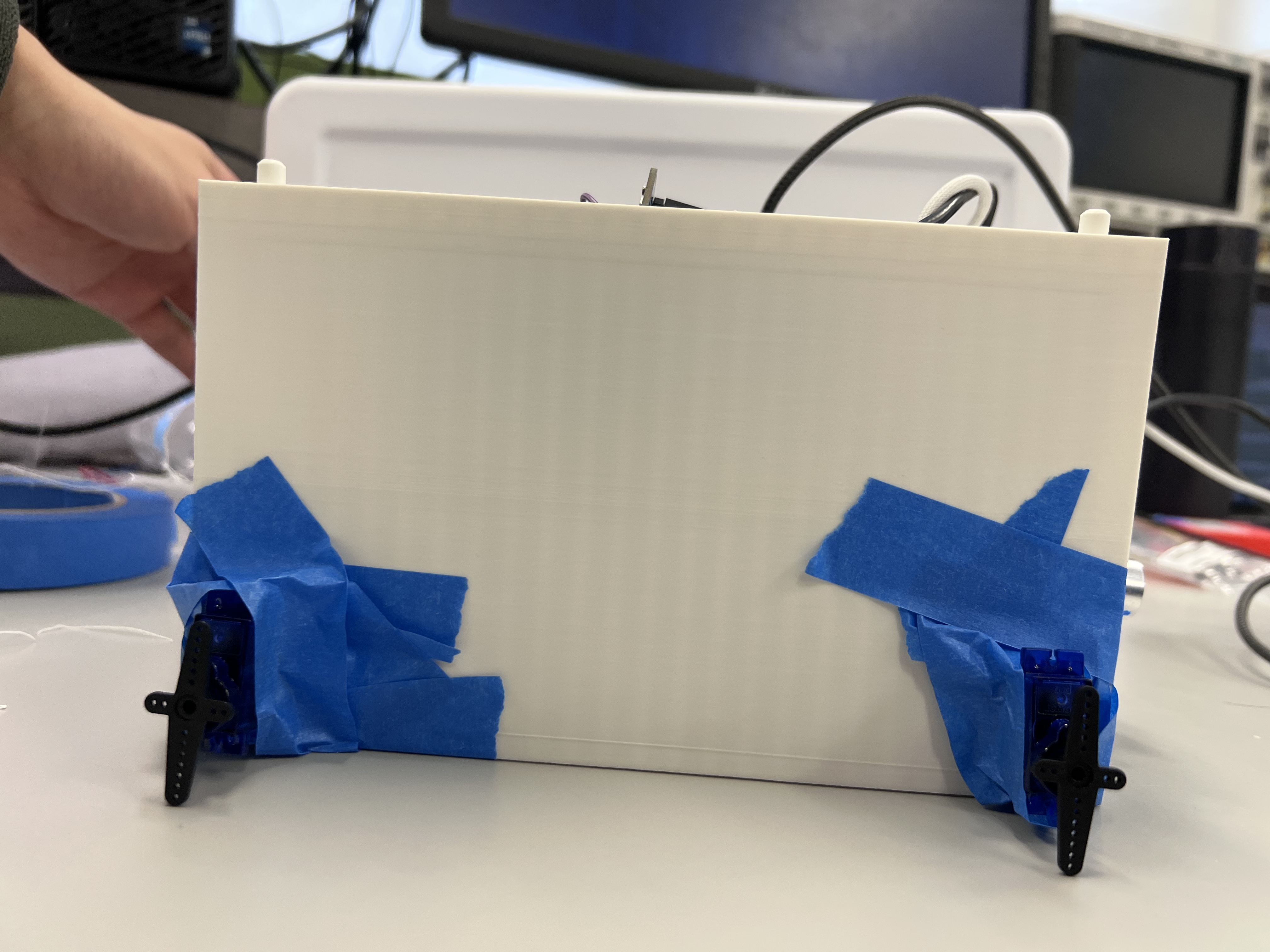
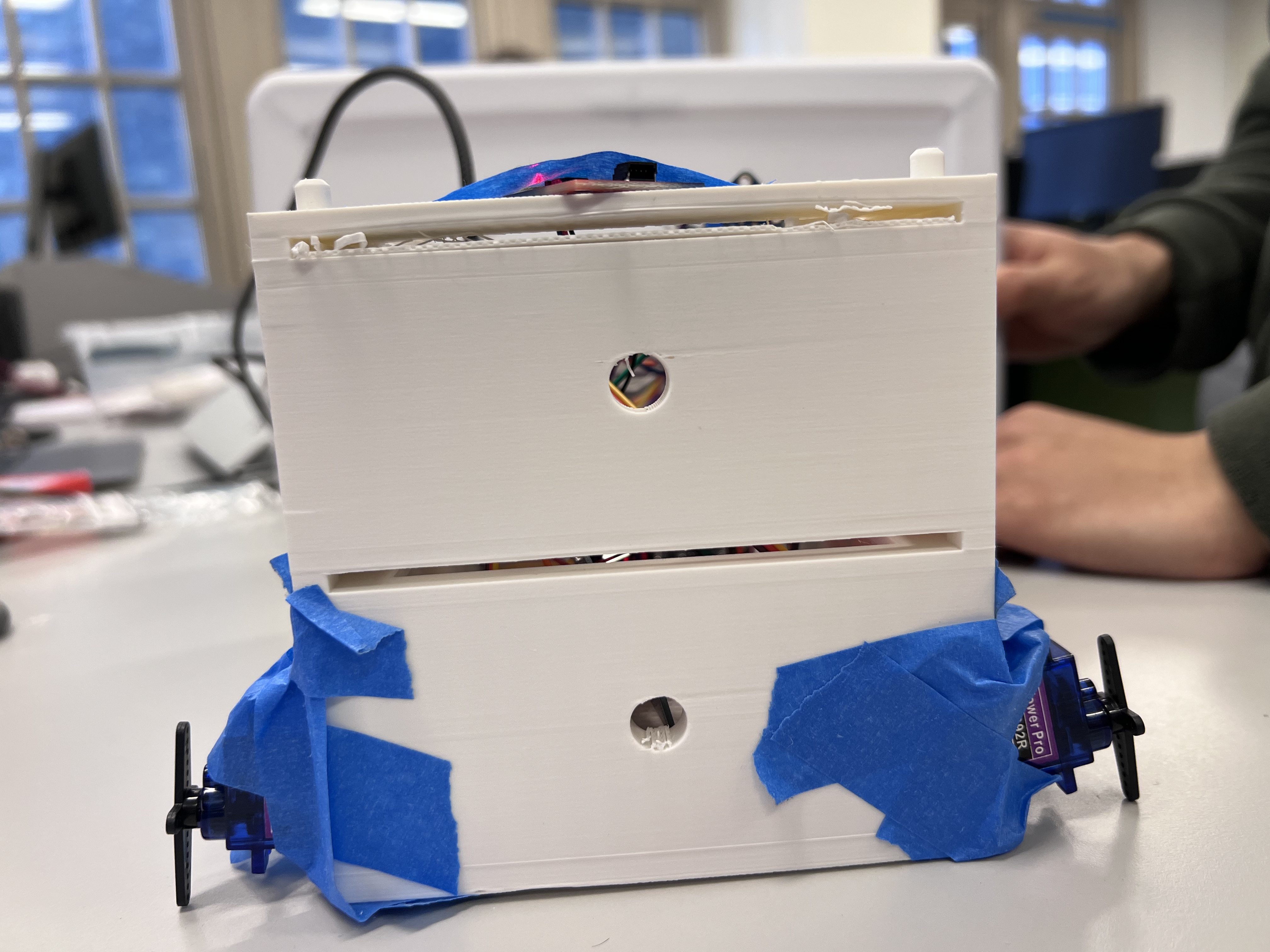
From this final program, I have learned much more about the I2C and I2S protocols and gained a comprehensive understanding of how to integrate different modules of code. I was responsible for 3D printing, ESP32 modeling, and the PWM generator. I also learned more about servo motors and how to use Arduino for voice recognition.At the beginning, we planned to use the ATmega328PB for voice recognition through the ADC. However, after integrating the code, we found a significant delay, which prevented us from achieving our goals. Therefore, we decided to use a microphone connected to the ESP32 and performed voice recognition on the ESP32 instead. This greatly reduced the delay in the overall system.One of the challenges we encountered was measuring the size of the servo motors because no dimensional information was provided in the datasheet. As a result, the hole size in our 3D-printed model did not match the servo motor dimensions. We had to use tape to wrap the motor to ensure it remained stable. In the next step, we could design and 3D-print a more realistic leg for our robot dog. We could also create a more suitable frame to eliminate the need for tape and improve overall stability.
References
UART library
LCD library (Lab 4 Pong).