guitar-hero-reversal.github.io
Guitar Hero Guitar to Synthesizer Conversion
| Panos Dimtsoudis | panosdim@seas.upenn.edu |
| Adam Shalabi | adamshal@seas.upenn.edu |
| Brandon Parkansky | bpar@seas.upenn.edu |
Demo Video
Watch our final project demonstration below.
(https://drive.google.com/drive/folders/1ST56ldJqHs8GEl2x1VyzHi_KoGJQNoxZ?dmr=1&ec=wgc-drive-%5Bmodule%5D-goto)
Final Product Images
Exterior View
Internal Electronics
Internals Tour: (https://drive.google.com/drive/folders/1iD0F-Pdt6Mc-L7aRFF9-XCKdbJgDcia5?dmr=1&ec=wgc-drive-%5Bmodule%5D-goto)
Showcase Thumbnail (400x400)
Project Overview
Our project converts a Guitar Hero controller into a playable electronic synthesizer using an ATmega328PB microcontroller. Colored fret buttons select musical notes while the speaker outputs synthesized PWM audio signals. A potentiometer-based Whammy Stick adds vibrato to the output wave when twisted. The LCD screen allows the user to see thier selected pitch for each button and change the pitch using the joystick. The strum bar at the center of the guitar turns activates sound output, playing the note of the corresponding pressed button when the guitar is strummed and fret switch closes, with the note slowly decaying to emulate a real strum. The goal was to combine embedded systems, signal generation, hardware interfacing, and creative design into an interactive musical instrument.
Software Requirements Specification (SRS) Results
| ID | Description | Validation Outcome |
|---|---|---|
| SRS-01 | The system shall read the guitar pitch buttons and determine the selected note or chord when a button is pressed. | CONFIRMED: As buttons pressed, code attributes key (as tested in serial monitor shown in MVP demo, and heard in sound output). |
| SRS-02 | When the user actuates the strum bar, the MCU shall generate and output the corresponding pitch control signal and gate signal. | CONFIRMED: Note plays when strummed |
| SRS-03 | The system shall read the whammy input through the ADC and update pitch bend during active note playback. | CONFIRMED: ADC detects whammy adjustments, vibrato added through code at threshold. |
| SRS-04 | The system shall support a mute function that disables note output when the mute button being pressed. | CONFIRMED: Mute button pulls mute pin, PWM stops when pressed. |
| SRS-05 | The firmware shall continuously monitor all required inputs during operation, including pitch buttons, strum bar, mute button, joystick, and whammy control, without causing the system to miss valid note-trigger events during normal use. | CONFIRMED: Essential inputs trigger interrupt, there is no latency or missed events when playing device. |
| SRS-06 | The display and joystick-based UI shall allow the user to change at least one synth setting (such as waveform, octave, or mode), and the selected setting shall be updated on the display. | CONFIRMED: Joystick controls screen, user can change configuration of notes, selection shows onscreen. |
Overall, our software requirements were successfully fulfilled. The most difficult feature on the software side was the screen, as fitting elements to the right size and maintaining readable contrast between options proved harder than expected, along with overall miscommunications between the joystick and screen function. We almost scrapped the screen feature entirely. However, after hours debugging, we were able to get the screen to a satisfying working state. Proof of software functionality (screen, input reading & output, etc) can be seen in the comprehensive video demo (linked above).
Hardware Requirements Specification (HRS) Results
| ID | Description | Validation Outcome |
|---|---|---|
| HRS-01 | The system shall use an ATmega328PB-based control system to interface with all required user inputs, including the pitch buttons, strum input, mute button, joystick, and whammy control | CONFIRMED: ATMega has all input and output pins (pitch, strum, mute, joystick, whammy). |
| HRS-02 | The system shall include a ADC-based pitch CV generation stage capable of producing a stable control signal for the synthesizer sound. | |
| HRS-03 | The system shall include an audio output stage consisting of a buffer and power amplifier capable of driving a speaker or external audio output. | CONFIRMED: buffer and amp circuit drives the speaker. |
| HRS-04 | The system shall include a display module for showing menu or mode information and shall communicate with the MCU using a supported serial protocol such as I2C . | CONFIRMED: Screen working, communicates with ATMega through I2C |
We mostly stayed true to our hardware requirements, aside from the ADC based pitch generation stage. When building out the hardware, we realized that a physical analog-based synthesizer would not be feasible or provide much value to the project compared to handling sound output through software, and decided to instead reduce complexity in our sound output hardware (synth output prototype is pictured below). Hardware requirement proof can be seen in the internals tour, linked above.
Challenges / Obstacles
While we faced many obstacles building this guitar, both those that caused us to change direction adn those that aligned with the original vision which broke physically or were buggy during testing, the most concerning obstacle was power regulation. When testing our MVP demo, we drove a speaker without a dedicated amplifier and powered our entire system via the ATMega 5V port. As a result, the speaker drew far too much power upon playing the guitar, and only after overloading several ATMegas did we realize the root issue. To solve this, we used a 12V battery pack with a 5V LDO to power the speaker and microcontroller, which fixed the issue of the system shutting down entirely. However, we ran into a new issue: the LDO made the speaker signal extremely noisy, and only after adding another 5V LDO did our guitar work entirely as intended.
Conclusion
Originally, we thought this project would be much easier than it actually was. During brainstorming, we planned advanced features such as filters, selectable waveform types (sine, square, sawtooth), and even modes that could imitate the sound of real guitars. In practice, we learned that embedded systems projects require strong prioritization. We had to reduce scope and focus on building a reliable product with the core features functioning well rather than attempting too many unstable additions.
One of the strongest outcomes was the final build quality. Earlier in development, we dealt with loose wiring, unreliable connections, inconsistent signals, and an overall messy prototype. By the end of the project, the final device was much cleaner, more organized, and significantly more robust.
We are especially proud that we transformed a Guitar Hero controller into a functional synthesizer that users can actually interact with. We are also proud that despite repeated setbacks, we continued iterating until we had a polished final product that looked presentable and operated consistently.
We gained practical experience integrating hardware and software into a complete embedded product. This project reinforced the importance of debugging systematically, managing project scope, testing power systems carefully, and designing around real-world hardware constraints rather than ideal assumptions.
We largely stayed true to our hardware requirements, aside from the original ADC-based pitch generation stage. As development progressed, we realized that a fully analog hardware synthesizer would add major complexity without significantly improving the user experience. Instead, we shifted toward software-driven sound synthesis using the microcontroller, simplifying the hardware while still achieving the intended functionality.
Earlier power-system planning and staged subsystem testing would have saved significant time. We initially focused heavily on functionality without giving enough attention to current draw, signal quality, and voltage regulation.
Power regulation became the largest unexpected obstacle. Initially, we assumed that supplying 5V everywhere would be sufficient. During early demos, we powered the system through the ATmega 5V rail while directly driving the speaker without a dedicated amplifier. This caused excessive current draw and repeatedly shut down or damaged components. We solved this by switching to a 12V battery pack with a 5V LDO regulator. However, this introduced severe speaker noise, which required adding an additional regulator stage before the system functioned reliably. This taught us that power design is just as important as logic design.
If continued, future improvements would include waveform selection, filters, pitch effects, and song-learning mode functionality where a screen highlights notes in real time to teach users how to play songs.
Project ReadMe:

Final Project
Team Number: 03
Team Name: Synth Specialists
| Team Member Name | Email Address |
|---|---|
| Adam Shalabi | adamshal@seas.upenn.edu |
| Brandon Parkansky | bpar@seas.upenn.edu |
| Panos Dimtsoudis | panosdim@seas.upenn.edu |
GitHub Repository URL: https://github.com/upenn-embedded/final-project-s26-t03.git
GitHub Pages Website URL: [for final submission]*
Final Project Proposal
1. Abstract
Our project repurposes an old toy guitar controller into an embedded music-learning device. The controller’s buttons will be programmable and mapped to individual notes or chords, while the strum bar will trigger sound generation. The sound will be produced by a synthesizer that we will design and build, and features like a mute button, whammy stick, and small display will make the device more expressive and customizable.
2. Motivation
Our motivation for choosing this project is that it combines hardware reuse with a meaningful educational application. Rather than leaving an obsolete gaming peripheral unused, we saw an opportunity to redesign it into a low-cost and engaging platform for teaching fundamental music concepts such as notes, chords, and pitch variation. The main problem we are trying to solve is that beginner music tools are often either too limited, too expensive, or not very interactive. By reusing an existing guitar controller and pairing it with a custom-built synthesizer, we can create a more hands-on and accessible way for users to learn basic musical ideas. This project is interesting because it combines embedded systems, digital sound generation, and interface design, while also showing how outdated electronics can be transformed into practical and creative learning tools.
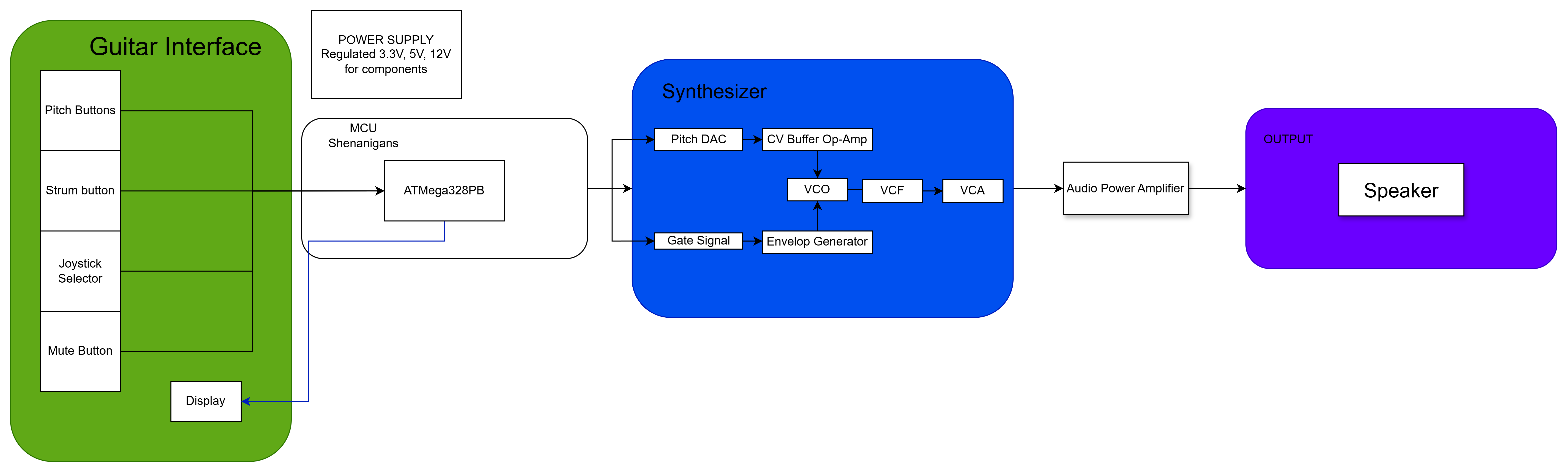
3. System Block Diagram
4. Design Sketches
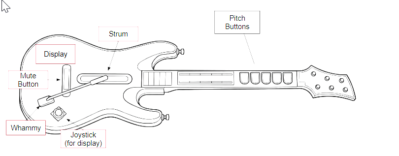
5. Software Requirements Specification (SRS)
5.1 Definitions, Abbreviations
MCU : ATmega328PB microcontroller
DAC : Digital-to-Analog Converter
VCO : Voltage-Controlled Oscillator
VCF : Voltage-Controlled Filter
VCA : Voltage-Controlled Amplifier
CV : Control Voltage
UI : User Interface
5.2 Functionality
| ID | Description |
|---|---|
| SRS-01 | The system shall read the guitar pitch buttons and determine the selected note or chord when a button is pressed. |
| SRS-02 | When the user actuates the strum bar, the MCU shall generate and output the correspondingpitch control signal and gate signal. |
| SRS-03 | The system shall read the whammy input through the ADC and update pitch bend during active note playback. |
| SRS-04 | The system shall support a mute function that disables note output when the mute button being pressed. |
| SRS-05 | The firmware shall continuously monitor all required inputs during operation, including pitch buttons, strum bar, mute button, joystick, and whammy control, without causing the system to miss valid note-trigger events during normal use |
| SRS-06 | The display and joystick-based UI shall allow the user to change at least one synth setting (such as waveform, octave, or mode), and the selected setting shall be updated on the display. |
6. Hardware Requirements Specification (HRS)
6.1 Definitions, Abbreviations
SPI : Serial Peripheral Interface
I2C : Inter-Integrated Circuit
ADC : Analog-to-Digital Converter
PWM : Pulse-Width Modulation
6.2 Functionality
| ID | Description |
|---|---|
| HRS-01 | The system shall use an ATmega328PB-based control system to interface with all required user inputs, including the pitch buttons, strum input, mute button, joystick, and whammy control |
| HRS-02 | The system shall include a ADC-based pitch CV generation stage capable of producing a stable control signal for the synthesizer voice |
| HRS-03 | The system shall include an audio output stage consisting of a buffer and power amplifier capable of driving a speaker or external audio output |
| HRS-04 | The system shall include a display module for showing menu or mode information and shall communicate with the MCU using a supported serial protocol such as I2C . |
7. Bill of Materials (BOM)
https://docs.google.com/spreadsheets/d/1yVx339OijMxmClf8FyQ_4eZAxMqQx_l-zpqn3cilw3A/edit?usp=sharing
8. Final Demo Goals
We will first demonstrate the functionality of the joystick selector and display by setting the buttons to specific chords. We will then play a song and showcase our synthesizer pitch bending with the whammy stick.
9. Sprint Planning
| Milestone | Functionality Achieved | Distribution of Work |
|---|---|---|
| Sprint #1 | Get Guitar and MCU communicating | Everyone works, if unfinished Adam will finish |
| Sprint #2 | Complete MCU Code (Synth) | Everyone works, if unfinished Panos will finish |
| MVP Demo | Make Synth and Speaker work | Everyone works (Adam and Panos focus on hardware, Brandon focus on code), if unfinished Brandon will finish. |
| Final Demo | Add Display and Whammy Stick | Everyone works together to assemble final product. If something breaks, member who had most input on this part will lead in fixing. |
This is the end of the Project Proposal section. The remaining sections will be filled out based on the milestone schedule.
Sprint Review #1
Last week’s progress
We took apart the original guitar and tested each interface button, stick and switch with a multimeter to make sure current flowed through them and they were functional. We decided to pivot from an analog synthesizer to a digital synthesizer that operates off of code, and created the first draft of this code for our intial test. We also noticed that the main board which we’d be replacing in the guitar did not fit properly with the internals, so we created a CAD model of the board to laser cut a new one with more leeway in the measurements for the openings to make it slot in seamlessly.
Current state of project
We’re still waiting on the remainder of our parts to come in so we can assmeble the system, flash the code and run our intial tests, but for now we’ve decided to pivot our strategy from connecting only through jumper wires to instead running connections through copper tape on our new iteration of the internal board, as per our team manager’s suggestion.
Next week’s plan
Build the first full working version of the guitar, test the existing code and mke changes as needed, then begin adding LCD screen functionality.
Sprint Review #2
Last week’s progress
We built a breadboarded prototype of the system with the parts available in detkin since our ADC and a few other Adafruit parts still hadn’t come in. We had to make a few code changes to account for the difference in functionality due to the lack of an ADC but eventually got decent sound output as desired, then wired up the LCD display though it still isn’t functional and doesn’t correspond to notes/inputs like we want it to.
Current state of project
We have a working prototype and are considering using the same no-ADC method in our MVP to reduce complexity and get a full built working version as soon as possible.
Next week’s plan
Print the main master board and solder the system using the wiring format we’ve used in our prototype and fit it to the actual guitar, fix the LCD screen to at least show some response to inputs even if it isn’t fully functional yet.
MVP Demo
Final Report
Don’t forget to make the GitHub pages public website! If you’ve never made a GitHub pages website before, you can follow this webpage (though, substitute your final project repository for the GitHub username one in the quickstart guide): https://docs.github.com/en/pages/quickstart
1. Video
2. Images
3. Results
3.1 Software Requirements Specification (SRS) Results
| ID | Description | Validation Outcome |
| —— | ——————————————————————————————————— | ——————————————————————————————- |
| SRS-01 | The system shall read the guitar pitch buttons and determine the selected note or chord when a button is pressed. | CONFIRMED: As buttons pressed, code attributes key (as tested in serial monitor shown in MVP demo, and heard in sound output).
| SRS-02 | When the user actuates the strum bar, the MCU shall generate and output the corresponding pitch control signal and gate signal. | CONFIRMED: Note plays when strummed
| SRS-03 | The system shall read the whammy input through the ADC and update pitch bend during active note playback. | CONFIRMED: ADC detects whammy adjustments, vibrato added through code at threshold.
| SRS-04 | The system shall support a mute function that disables note output when the mute button being pressed. | CONFIRMED: Mute button pulls mute pin, PWM stops when pressed.
| SRS-05 | The firmware shall continuously monitor all required inputs during operation, including pitch buttons, strum bar, mute button, joystick, and whammy control, without causing the system to miss valid note-trigger events during normal use. | CONFIRMED: Essential inputs trigger interrupt, there is no latency or missed events when playing device.
| SRS-06 | The display and joystick-based UI shall allow the user to change at least one synth setting (such as waveform, octave, or mode), and the selected setting shall be updated on the display. | CONFIRMED: Joystick controls screen, user can change configuration of notes, selection shows onscreen.
/
3.2 Hardware Requirements Specification (HRS) Results
| ID | Description | Validation Outcome |
|---|---|---|
| HRS-01 | The system shall use an ATmega328PB-based control system to interface with all required user inputs, including the pitch buttons, strum input, mute button, joystick, and whammy control | CONFIRMED: ATMega has all input and output pins (pitch, strum, mute, joystick, whammy). |
| HRS-02 | The system shall include a ADC-based pitch CV generation stage capable of producing a stable control signal for the synthesizer voice. | |
| HRS-03 | The system shall include an audio output stage consisting of a buffer and power amplifier capable of driving a speaker or external audio output. | CONFIRMED: buffer and amp circuit drives the speaker. |
| HRS-04 | The system shall include a display module for showing menu or mode information and shall communicate with the MCU using a supported serial protocol such as I2C . | CONFIRMED: Screen working, communicates with ATMega through I2C |